
Host controlled voltage input system for an accessory device

a voltage management system and accessory device technology, applied in the direction of electric variable regulation, process and machine control, instruments, etc., can solve the problems of increasing the cost and complexity of the accessory and measurement test instrument interface, increasing the complexity and cost of the measurement test instrumen

Active Publication Date: 2009-05-12
TEKTRONIX INC
View PDF44 Cites 75 Cited by
  • Summary
  • Abstract
  • Description
  • Claims
  • Application Information

AI Technical Summary

Problems solved by technology

This increases the complexity and cost of the measurement test instrument as well as increasing the cost and complexity of the accessory and measurement test instrument interface.

Method used


Image

  • Host controlled voltage input system for an accessory device
  • Host controlled voltage input system for an accessory device
  • Host controlled voltage input system for an accessory device

Examples


Embodiment Construction

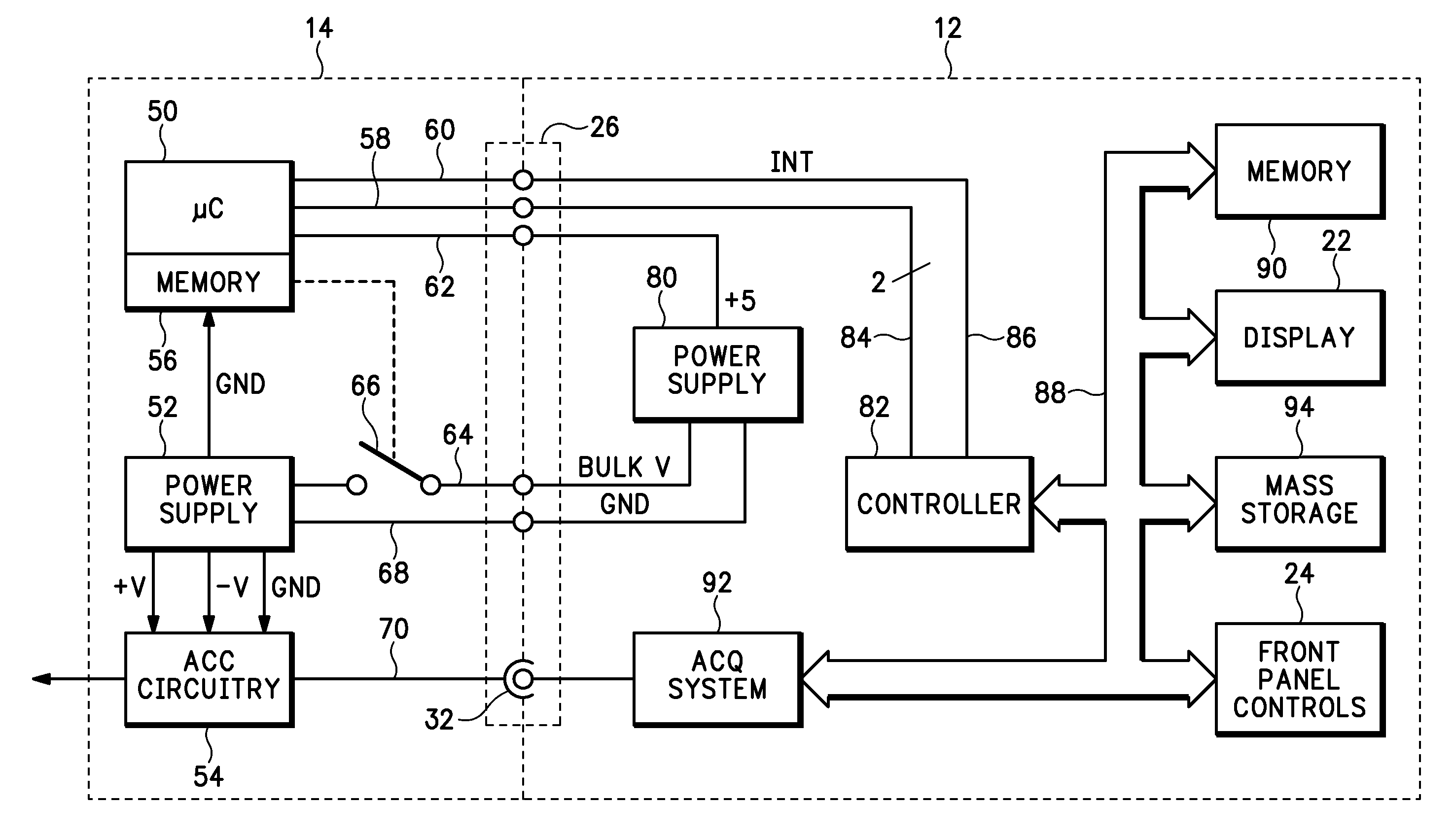
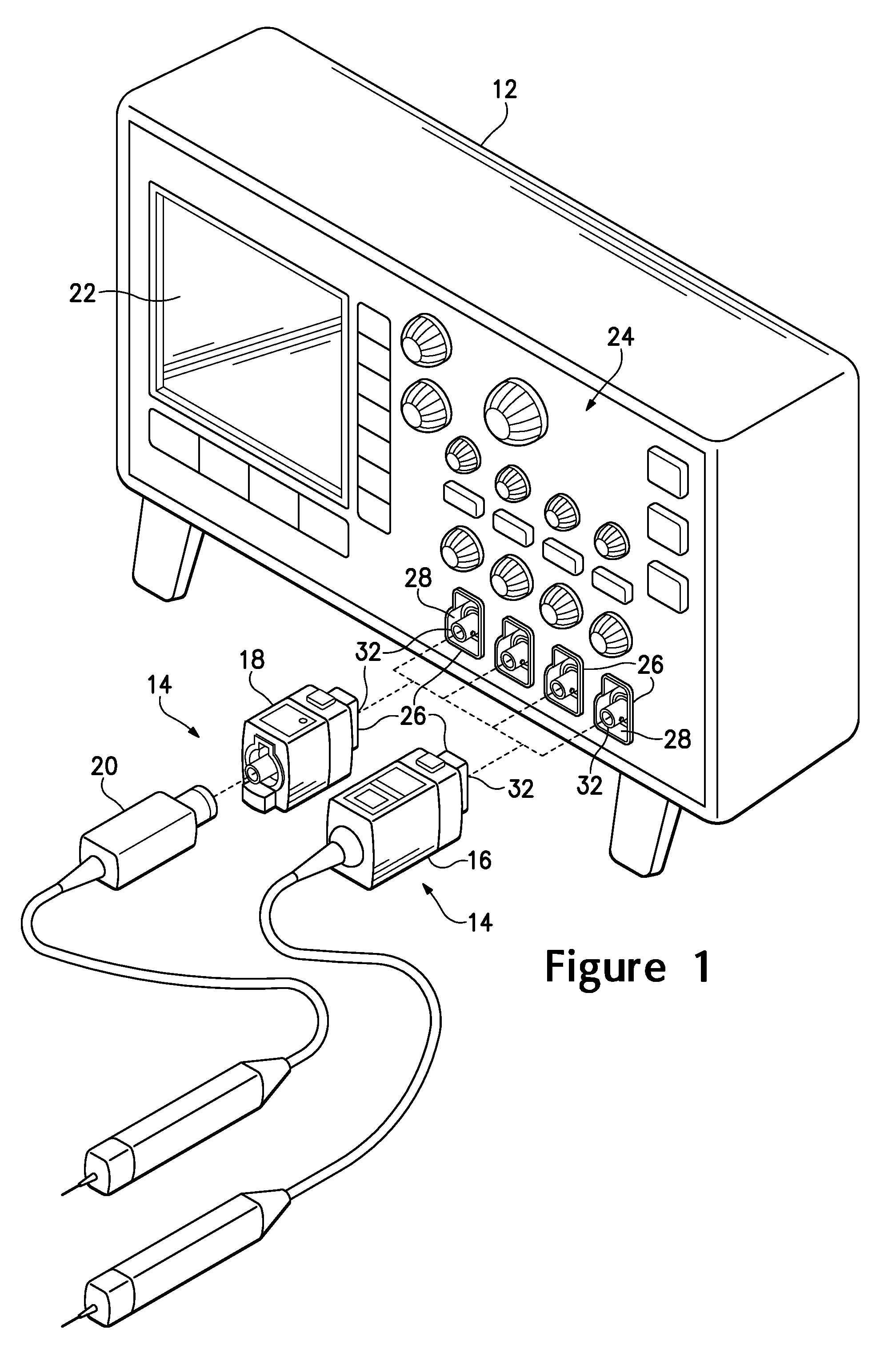
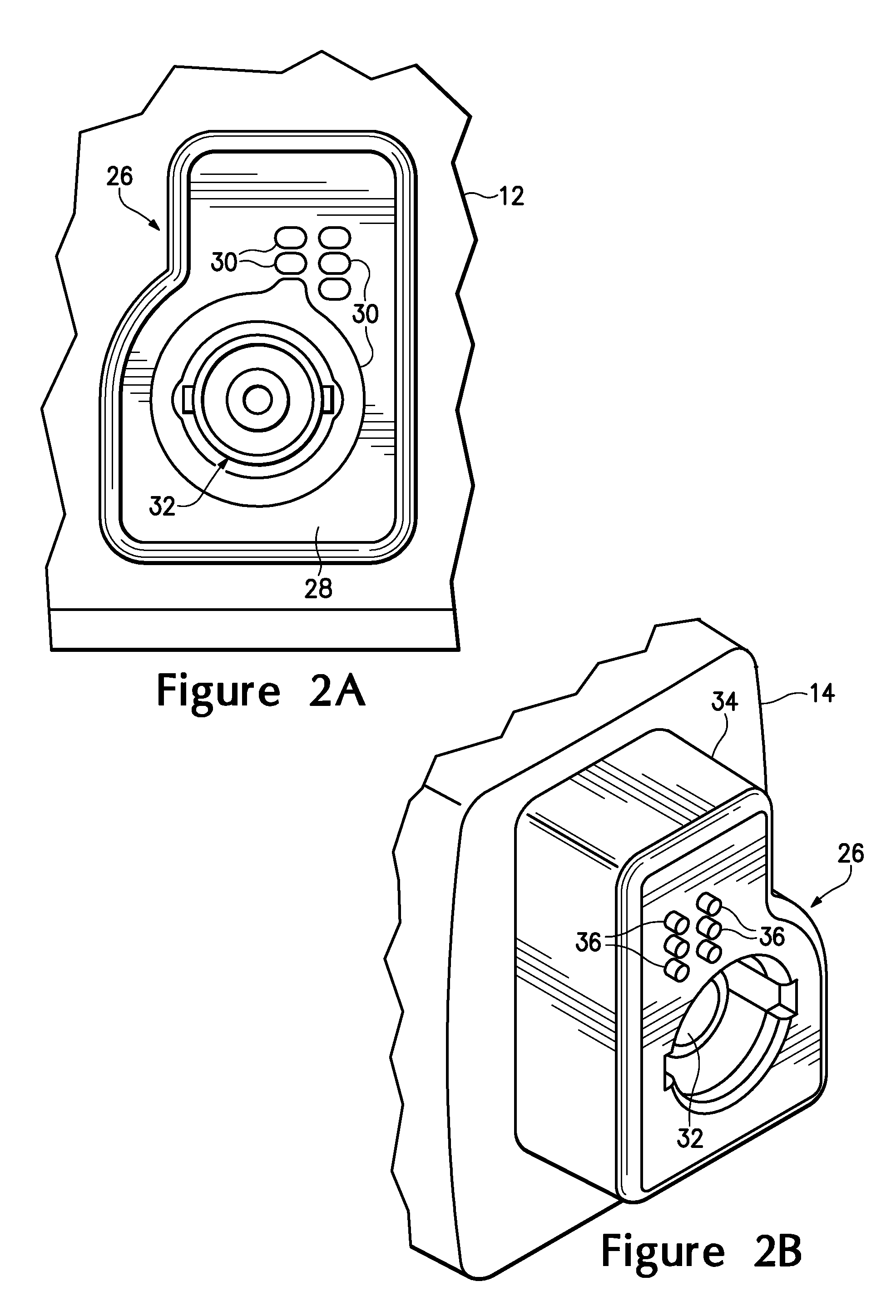
[0017]Referring to FIG. 1, there is shown a perspective view of a host 12 and accessory device 14 having an accessory device voltage management system. The host 12 is representatively shown as a measurement test instrument, such as an oscilloscope. The host may be other type of measurement test instruments, such as a logic analyzer, spectrum analyzer and the like, or other types of host devices that provide power to an accessory device. The accessory device 14 is representatively shown as a measurement probe 16 or measurement probe adapter 18 that receives a measurement probe 20. The measurement probes 16 and 20 may be passive or active voltage probes, current probes or the like. The accessory device 14 may also be a video or thermal camera, optical-to-electrical converter, active pre-filter or other transducer devices or general accessory device requiring power from the host 12, such as a calibration fixture, probe isolation accessory, serial data acquisition system or the like.

[00...


PUM


Abstract

An accessory device voltage management system includes an accessory device selectively coupled to a host. The host provides a bulk power supply and a low power supply voltage to the accessory device. The host receives accessory device parameters from the device and determines if the accessory device is a valid and supported device and, if so, sends commands to the accessory device to couple the bulk power supply voltage to a power supply circuit in the accessory device. The power supply circuit in the accessory device generates at least a first regulated voltage output.

Description

BACKGROUND OF THE INVENTION[0001]The present invention relates generally to providing a voltage to an accessory device and more particularly to an accessory device voltage management system controlled by a host.[0002]A typical measurement probe for acquiring electrical signals from a device under test has a probing head connected to a termination / control box via a transmission cable, such as a coaxial cable. The probing head may be for acquiring voltage or current signals. The probing head has passive and / or active circuitry for conditioning the acquired signal prior to coupling the signal to the termination / control box. The termination / control box has a coaxial signal connector, such as a BNC type connector, and may include power, clock and data connectors for connecting the measurement probe to a measurement test instrument, such as an oscilloscope or the like.[0003]U.S. Pat. No. 6,629,048 B1 teaches a measurement test instrument and associated voltage management system for an acc...

Claims


Application Information

Patent Timeline
Patent Type & Authority Patents(United States)
IPC IPC(8): H02M3/18H02M7/00
CPCG01R1/06788H02J7/34
Inventor DOBYNS, KENNETH P.MENDE, MICHAEL J.VAN EPPS, RICHARD A.STEVENS, MICHAEL D.
Owner TEKTRONIX INC
Learn More