Semiconductor display device and electronic appliance
a display device and semiconductor technology, applied in semiconductor devices, electrical appliances, instruments, etc., can solve the problems of increasing the drive frequency and more pseudo-contours in the pixel portion, so as to increase the number of gray scales, secure the writing period, and suppress the drive frequency of the driver circuit.
- Summary
- Abstract
- Description
- Claims
- Application Information
AI Technical Summary
Benefits of technology
Problems solved by technology
Method used
Image
Examples
embodiment 1
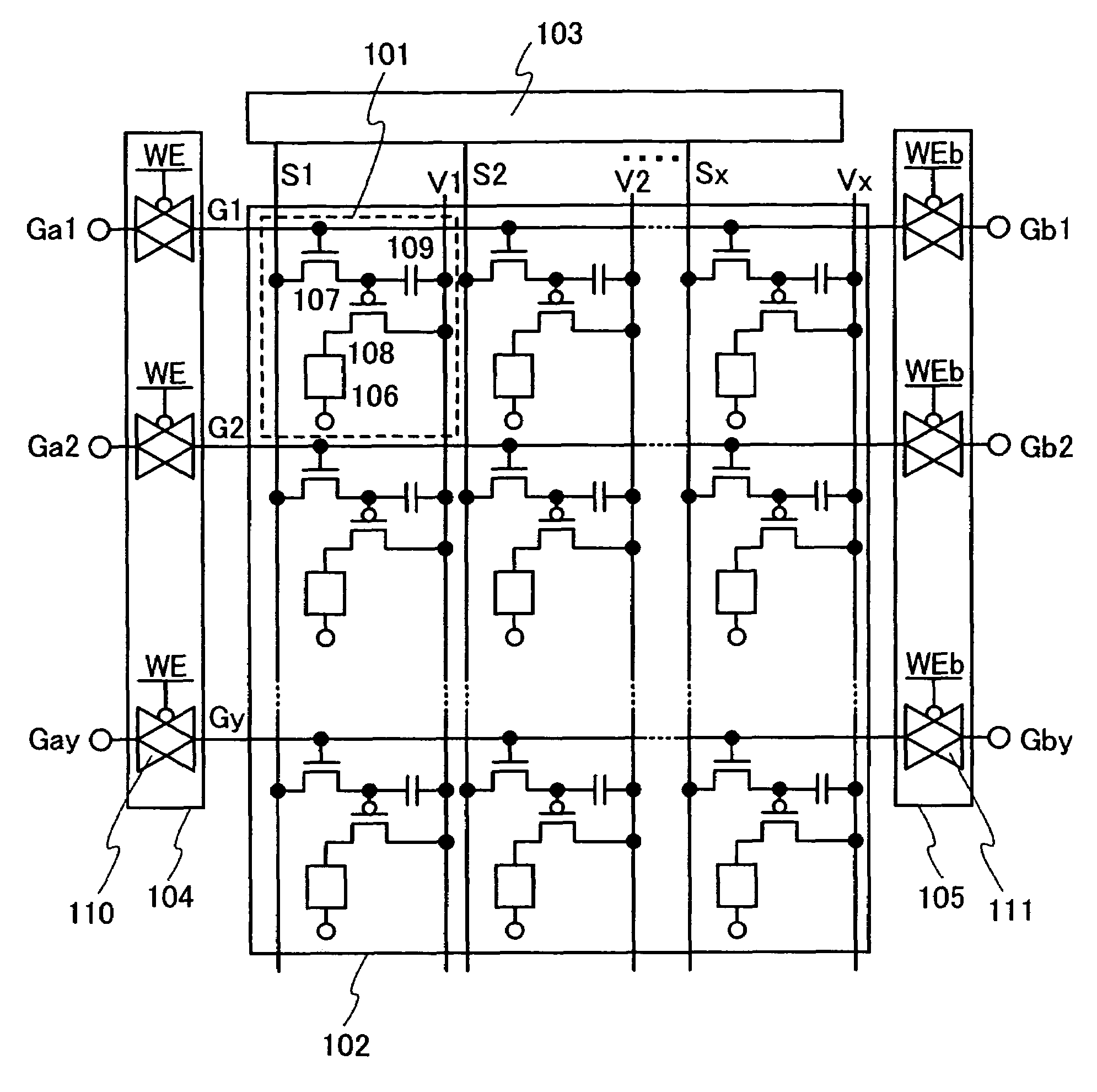
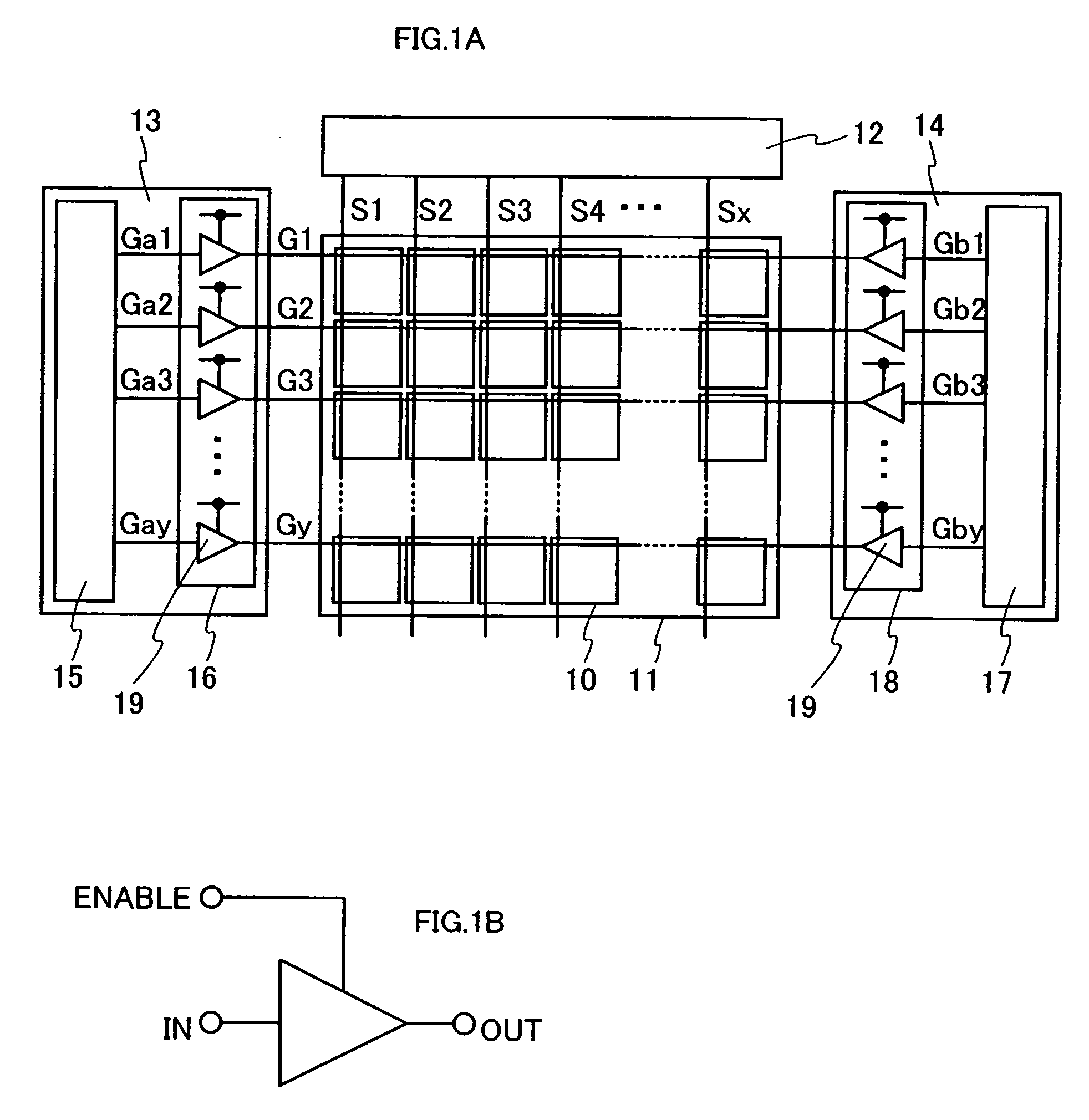
[0073]In this embodiment, description is made on a configuration of a driver circuit used in the semiconductor display device of the invention. FIG. 7 is a block diagram of the semiconductor display device of the invention. The semiconductor display device shown in FIG. 7 includes a pixel portion 200 where a plurality of pixels each having a display element such as a light-emitting element and a liquid crystal element are formed, first and second scan line driver circuits 201 and 202 for selecting each pixel, and a signal line driver circuit 203 for controlling an input of video signals to the selected pixel.
[0074]In FIG. 7, the signal line driver circuit 203 includes a shift register 204, a first latch 205, and a second latch 206. The shift register 204 is inputted with clock signals SCK for signal lines, and start pulse signals SSP for the signal lines. Upon input of the clock signals SCK and the start pulse signals SSP, the shift register 204 generates timing signals. The generat...
embodiment 2
[0082]In this embodiment, description is made in further detail on the operation of the signal line driver circuit 203 shown in FIG. 7. FIG. 8A is a block diagram of the signal line driver circuit 203. As described in Embodiment 1, the signal line driver circuit 203 includes the shift register 204, the first latch205, and the second latch 206. The shift register 204 is inputted with clock signals SCK, start pulse signals SSP, and inverted clock signals SCKb. The first latch 205 is inputted with video signals, and the second latch 206 is inputted with latch signals LP. Video signals inputted to the first latch 205 in a serial manner are inputted to the signal lines S1 to Sx in a parallel manner from the second latch 206.
[0083]FIG. 8B is a timing chart of the signal line driver circuit 203 shown in FIG. 8A. In synchronization with a start pulse signal SSP, a serial video signal having the data of Daj which corresponds to the pixels in the j-th row is written to the first latch 205.
[00...
embodiment 3
[0092]In this embodiment, description is made with reference to FIGS. 9A to 9C on the sectional structure of a pixel in the case where a P-channel driving transistor is employed. Note that FIGS. 9A to 9C each illustrates the case where a first electrode is an anode while the second electrode is a cathode; however, the first electrode may be a cathode while the second electrode may be an anode.
[0093]FIG. 9A is a sectional diagram of a pixel in the case where a P-channel transistor is used as a driving transistor 6001, and light emitted from a light-emitting element 6003 is extracted from a first electrode 6004.
[0094]The driving transistor 6001 is covered with an interlayer insulating film 6007, over which a bank 6008 having an opening portion is formed. In the opening portion of the bank 6008, the first electrode 6004 is partially exposed, and the first electrode 6004, an electroluminescent layer 6005, and a second electrode 6006 are stacked in this order.
[0095]The interlayer insulat...
PUM
 Abstract
Description
Claims
Application Information
 - R&D
- Intellectual Property
- Life Sciences
- Materials
- Tech Scout
- Unparalleled Data Quality
- Higher Quality Content
- 60% Fewer Hallucinations
Browse by: Latest US Patents, China's latest patents, Technical Efficacy Thesaurus, Application Domain, Technology Topic, Popular Technical Reports.
© 2025 PatSnap. All rights reserved.Legal|Privacy policy|Modern Slavery Act Transparency Statement|Sitemap|About US| Contact US: help@patsnap.com


