
Configurable filter and receiver incorporating same

a receiver and configuration technology, applied in the field of signal processing, can solve problems such as affecting the delay of filter integration during the first mode of operation, and achieve the effect of enhancing filter versatility and programmability

Active Publication Date: 2009-04-28
RAYTHEON CO
View PDF19 Cites 32 Cited by
  • Summary
  • Abstract
  • Description
  • Claims
  • Application Information

AI Technical Summary

Benefits of technology

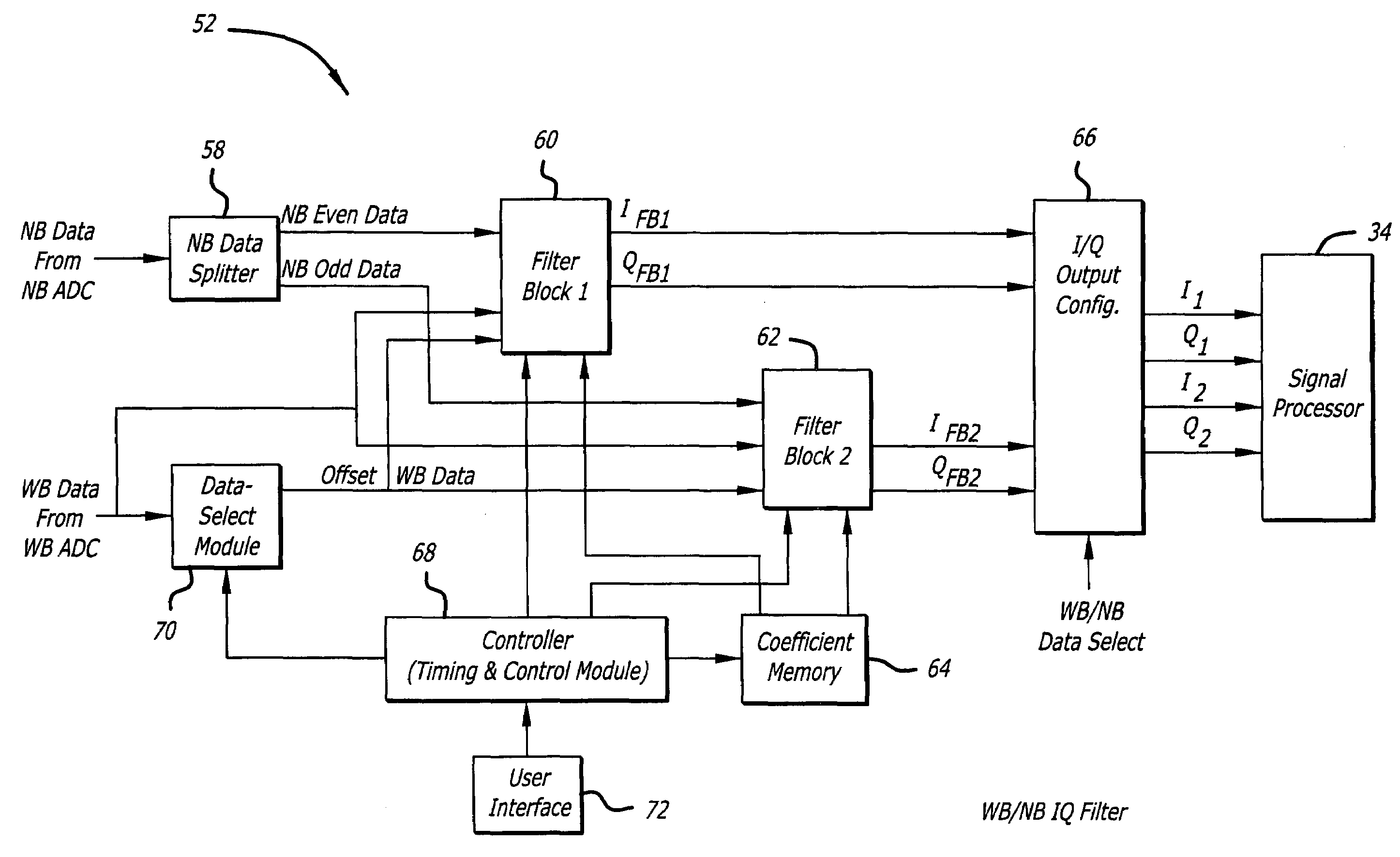
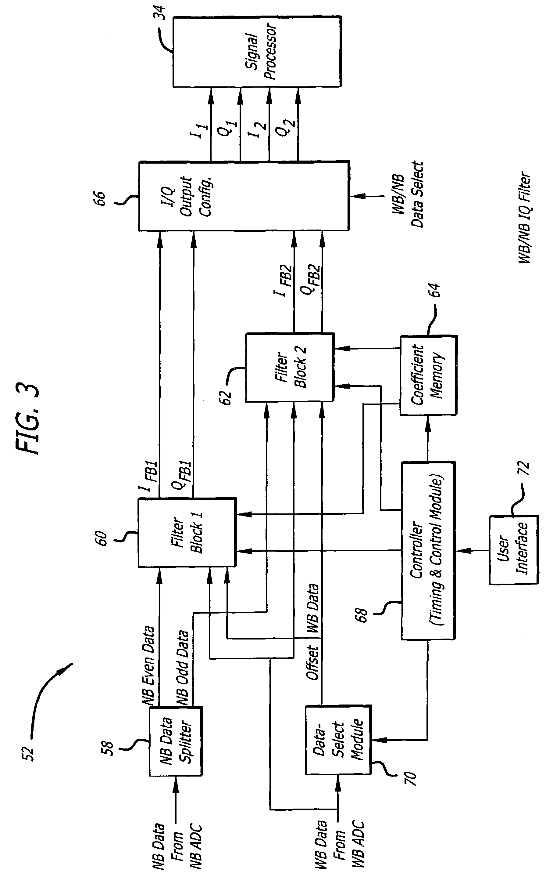
[0009]In a specific embodiment; the first type of signal is characterized by a first rate; and the second type of signal is characterized by a second rate. The first signal and the second signal are ADC output signals. The second mechanism includes plural filter banks, each filter bank associated with one or more Multiply-Accumulate (MAC) pipes. Each of the one or more MAC pipes include one or more MAC blocks that are each associated with a coefficient memory data structure. The third mechanism includes a controller that facilitates selecting coefficients from each memory data structure to apply to each of the one or more MAC blocks, thereby selectively affecting filter response. The coefficients are user-definable, and the controller is user-configurable via a user interface to the controller.
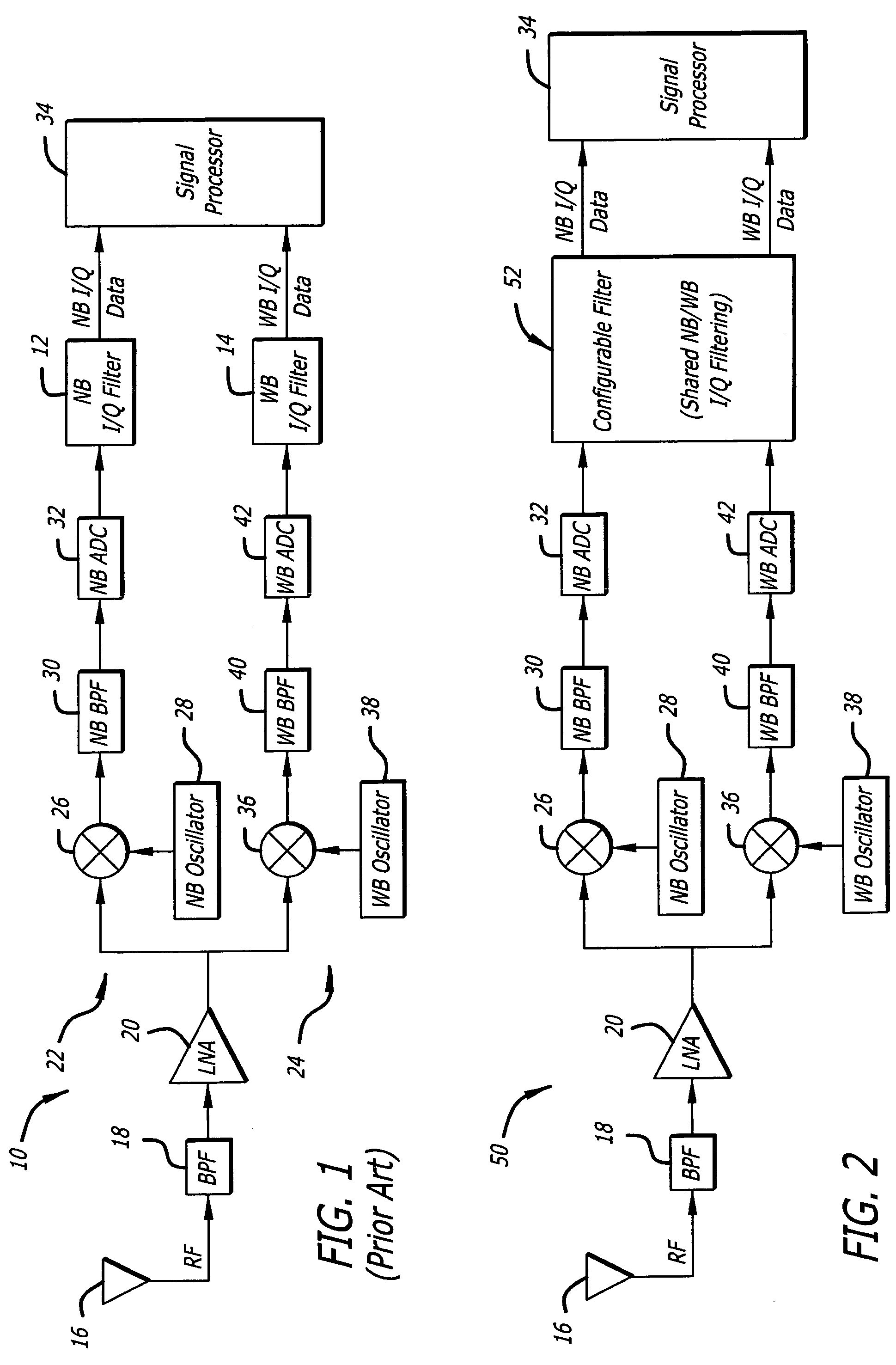
[0014]The novel design of one embodiment of the present invention is facilitated by the fourth mechanism, which enables the configurable filter to selectively process signals at different input data rates in accordance with appropriate filter responses. Accordingly, the configurable filter may be shared between wideband and narrowband data paths in various signal processors, such as radar receivers. Furthermore, use of shared filtering afforded by various embodiments of the present invention enable smaller receiver designs that may be implemented via a single FPGA rather than several FPGAs. Use of a versatile coefficient memory enables the filter response to be adjusted in accordance with predetermined criteria, such as the operational mode of the system. Furthermore, use of unique configurable filter blocks enables variations in filter integration delays, which enhances filter versatility and programmability.

Problems solved by technology

The specific control signals are configured to selectively switch a desired number of the multiplexers or switches to affect numbers of the MAC pipes that are connected in a serial configuration, thereby affecting filter integration delay during the first mode of operation.

Method used


Image

  • Configurable filter and receiver incorporating same
  • Configurable filter and receiver incorporating same
  • Configurable filter and receiver incorporating same

Examples


Embodiment Construction

[0022]While the present invention is described herein with reference to illustrative embodiments for particular applications, it should be understood that the invention is not limited thereto. Those having ordinary skill in the art and access to the teachings provided herein will recognize additional modifications, applications, and embodiments within the scope thereof and additional fields in which the present invention would be of significant utility.

[0023]The following discussion of a conventional receiver is intended to facilitate an understanding of the present invention.

[0024]FIG. 1 is a block diagram of a conventional receiver 10 employing a NarrowBand (NB) In-phase and Quadrature (I / Q) filter 12 for filtering narrowband data and a WideBand (WB) I / Q filter 14 for filtering wideband data. The conventional receiver 10 includes, from left to right, a Radio Frequency (RF) antenna 16, a first BandPass Filter (BPF) 18, and Low Noise Amplifier (LNA) 20. The output of the LNA 20 is s...


PUM


Abstract

An efficient configurable signal filter. The filter includes a first mechanism for receiving a first signal of a first type and a second signal of a second type. A second mechanism selectively filters the first signal during a first mode of operation, and filters the second signal during a second mode of operation. A third mechanism generates control signals. A fourth mechanism automatically configures the second mechanism to operate in the first mode of operation or the second mode of operation based on the control signals. In a specific embodiment, the first type of signal is characterized by a first rate, and the second type of signal is characterized by a second rate. The first signal and the second signal are digital ADC outputs. The second mechanism includes plural filter blocks, each having one or more Multiply-Accumulate (MAC) pipes. Each of the one or more MAC pipes include one or more MAC blocks that are each associated with a coefficient memory data structure of a coefficient memory. The third mechanism or a user selects coefficients from each memory data structure to apply to each MAC block, thereby selectively affecting filter response. The control signals direct multiplexers or switches to configure the MAC pipes in a serial configuration or a parallel configuration corresponding to the first mode of operation or the second mode of operation, respectively.

Description

[0001]This invention was made with Government support under Contract No. F19628-00-C-0100 awarded by the Department of the Air Force. The Government has certain rights in this invention.BACKGROUND OF THE INVENTION[0002]1. Field of Invention[0003]This invention relates to signal processing. Specifically, the present invention relates to filters, such as digital bandpass filters and accompanying receiver systems.[0004]2. Description of the Related Art[0005]Digital bandpass filters are employed in various demanding applications including digital radar receivers, multimode ladars, and spread spectrum communication systems. Such applications often employ plural bandpass filters to process digital signals at different rates.[0006]A signal processing system may include plural Analog-to-Digital Converters (ADCs), each providing digital outputs at different rates along different signal processing paths. Large and expensive Application-Specific Integrated Circuits (ASICs) or multiple Field-Pr...

Claims


Application Information

Patent Timeline
Patent Type & Authority Patents(United States)
IPC IPC(8): H04B1/10
CPCH03H17/0294H04B1/001H04B1/0017H04B1/28H03H2218/04
Inventor DAVIDOFF, LOAN T.NUSSBAUM, HOWARD S.CHIA, JACKSON Y.
Owner RAYTHEON CO
Learn More