
Safety shielding needle assembly with passive shielding

a needle and passive shielding technology, applied in the field of safety needle assembly, can solve the problems of unnecessary discomfort for patients, affecting the use of the skin to activate the device, and affecting the user's comfor

Active Publication Date: 2009-04-28
BECTON DICKINSON & CO
View PDF7 Cites 30 Cited by
  • Summary
  • Abstract
  • Description
  • Claims
  • Application Information

AI Technical Summary

Benefits of technology

[0014]The invention may include a biasing member biasing the retaining member away from engagement with the telescoping shield. Further, this biasing member may be positioned to be prevented from moving the retaining member away from engagement with the telescoping shield for a period of time following when the actuator is activated by pressure applied during the standard sequence of operation of the medical device. For example, the biasing member may be prevented from moving the retaining member out of engagement with the telescoping sleeve until the evacuated tube is removed from the needle holder.

Problems solved by technology

However, these shield arrangements have required the use of one or two hands to perform the operation of moving the shield over the contaminated needle, which is a hindrance to the user.
Such devices also require the internal diameter of the needle to be decreased, which may affect blood flow or require the external diameter of the needle to be enlarged and may cause unnecessary discomfort to the patient.
Using the skin to activate the device is not desirable since the device may not activate if the needle does not penetrate sufficiently or may cause the shield to inadvertently lock when probing for the vein.
Such devices may also require excessive penetration into some patients to cause the triggering means to activate the device, which will cause a phlebotomist to unnecessarily have to change their standard method or procedure.
Although providing significant improvements over the prior art systems, the system of the '239 and '845 patents involving deployment of the telescoping sleeve upon tube insertion can be a distraction to the user, in the event they must probe for the vein after shield is activated.

Method used


Image

  • Safety shielding needle assembly with passive shielding
  • Safety shielding needle assembly with passive shielding
  • Safety shielding needle assembly with passive shielding

Examples


Embodiment Construction

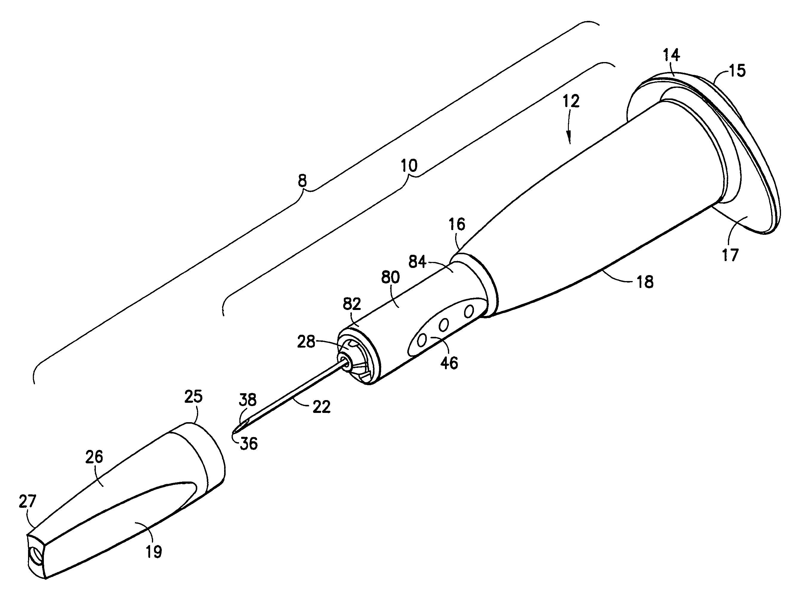
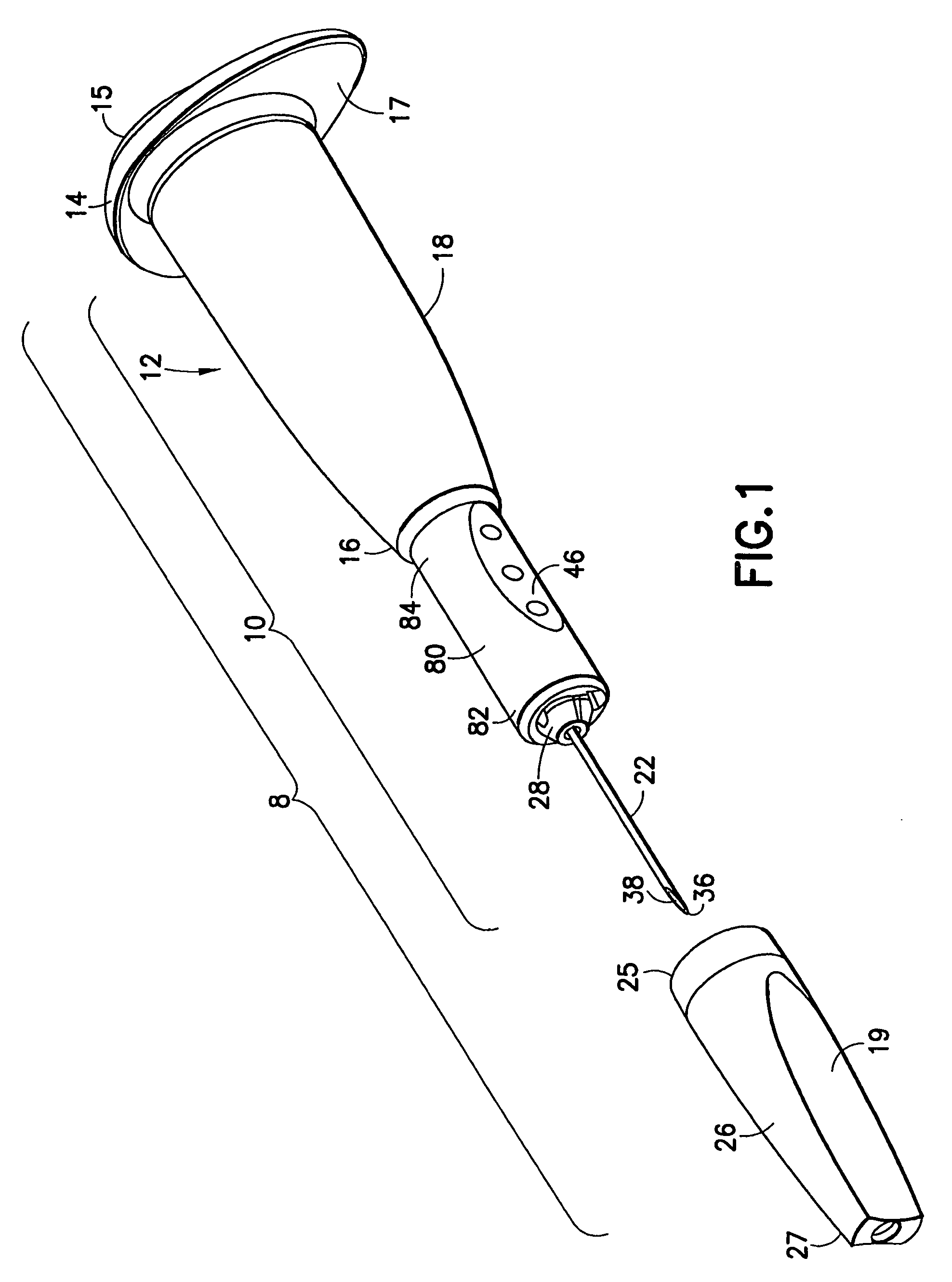
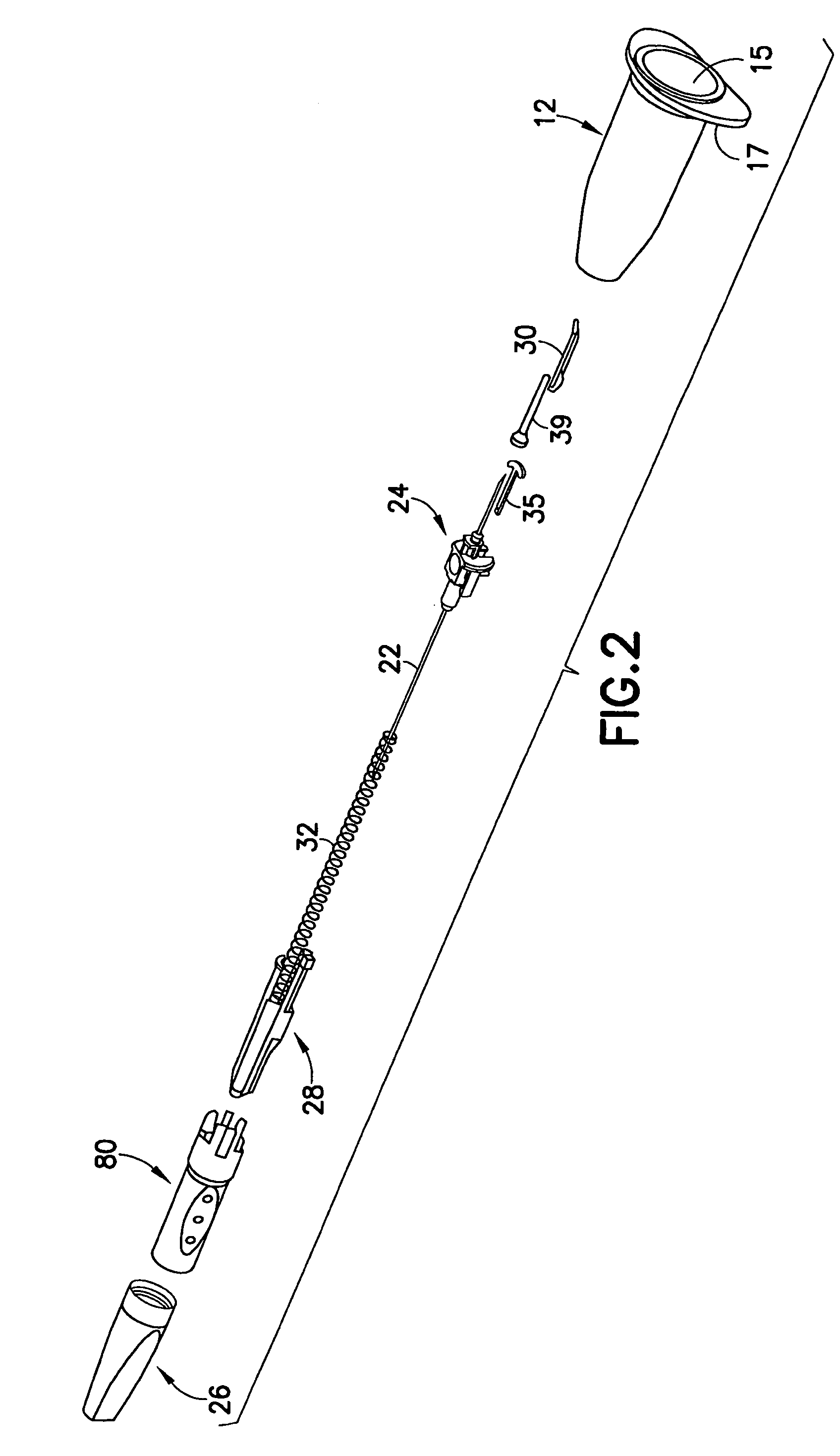
[0053]The needle assembly 10 of the present invention is shown in FIGS. 1-7 and 11-20. It will be noted that the term “distal” as used herein refers to the end of the needle assembly that punctures the patient's skin while “proximal” means the end of the needle assembly that punctures an evacuated container. Needle assembly 10 is mounted to a needle holder 12, as shown in FIGS. 1,3, and 4. Needle holder 12 has a proximal end 14, a distal end 16 and a tubular sidewall 18 extending between ends 14 and 16. Proximal end 14 of needle holder 12 is open and is adapted to receive a blood collection tube 20 as shown in FIGS. 17, 19A-19C, and 20A-20C. FIGS. 20A-20C omit the retaining member for clarity. However, proximal end 14 of holder 12 may have a removable seal or cap 15 for sterility. Proximal end 14 of holder 12 also has a radially aligned finger flange 17 to facilitate manipulation of holder 12. Flange 17 is a non-circular to prevent holder 12 from rolling. Flange 17 preferably has a ...


PUM


Abstract

A shieldable collection needle assembly that shields the needle upon tube withdrawal includes a hub mounted on a needle cannula and a spring biased telescoping shield mounted on the hub. The needle assembly is matable with a needle holder adapted to receive the blood collection tubes. The needle assembly includes a retaining member moveably mounted on the hub and engageable with the telescoping shield when the collection tube is positioned in the needle holder. The retaining member prevents the telescoping shield from moving toward the fully extended position when engaged therewith. The telescoping shield will move toward the fully extended position when the retaining member is disengaged from the telescoping shield following removal of the collection tube from the needle holder.

Description

RELATED APPLICATIONS[0001]This application claims priority on U.S. Provisional Patent Appl. No. 60 / 463,384 filed Apr. 16, 2003.BACKGROUND OF THE INVENTION[0002]1. Field of the Invention[0003]The present invention relates to a safety needle assembly with a telescoping shield that is activated during a standard sequence of operation of a medical procedure and, more particularly, relates to a needle and hub assembly having a telescoping shield that is activated when a sampling tube is removed from a needle holder.[0004]2. Description of the Related Art[0005]An evacuated collection tube, needle cannula (generally a double ended needle cannula) and needle holder are commonly used by a doctor, phlebotomist or nurse to draw a sample of body fluid from a patient in a hospital or doctor's office for diagnostic testing. During the use of such a collection needle assembly, the distal end of the needle cannula in the needle holder is inserted into the vein of the patient. The evacuated collecti...

Claims


Application Information

Patent Timeline
IPC IPC(8): A61M5/32A61M5/00A61B5/15A61B5/154
CPCA61B5/1444A61M5/326A61B5/15003A61B5/150259A61B5/150351A61B5/150389A61B5/150496A61B5/150549A61B5/150572A61B5/150648A61B5/150717A61B5/150732A61B5/154
Inventor CONWAY, HUGH T.
Owner BECTON DICKINSON & CO
Learn More