
Fastener and process for using same

Inactive Publication Date: 2009-04-28
STAFAST PROD
View PDF22 Cites 16 Cited by
  • Summary
  • Abstract
  • Description
  • Claims
  • Application Information

AI Technical Summary

Benefits of technology

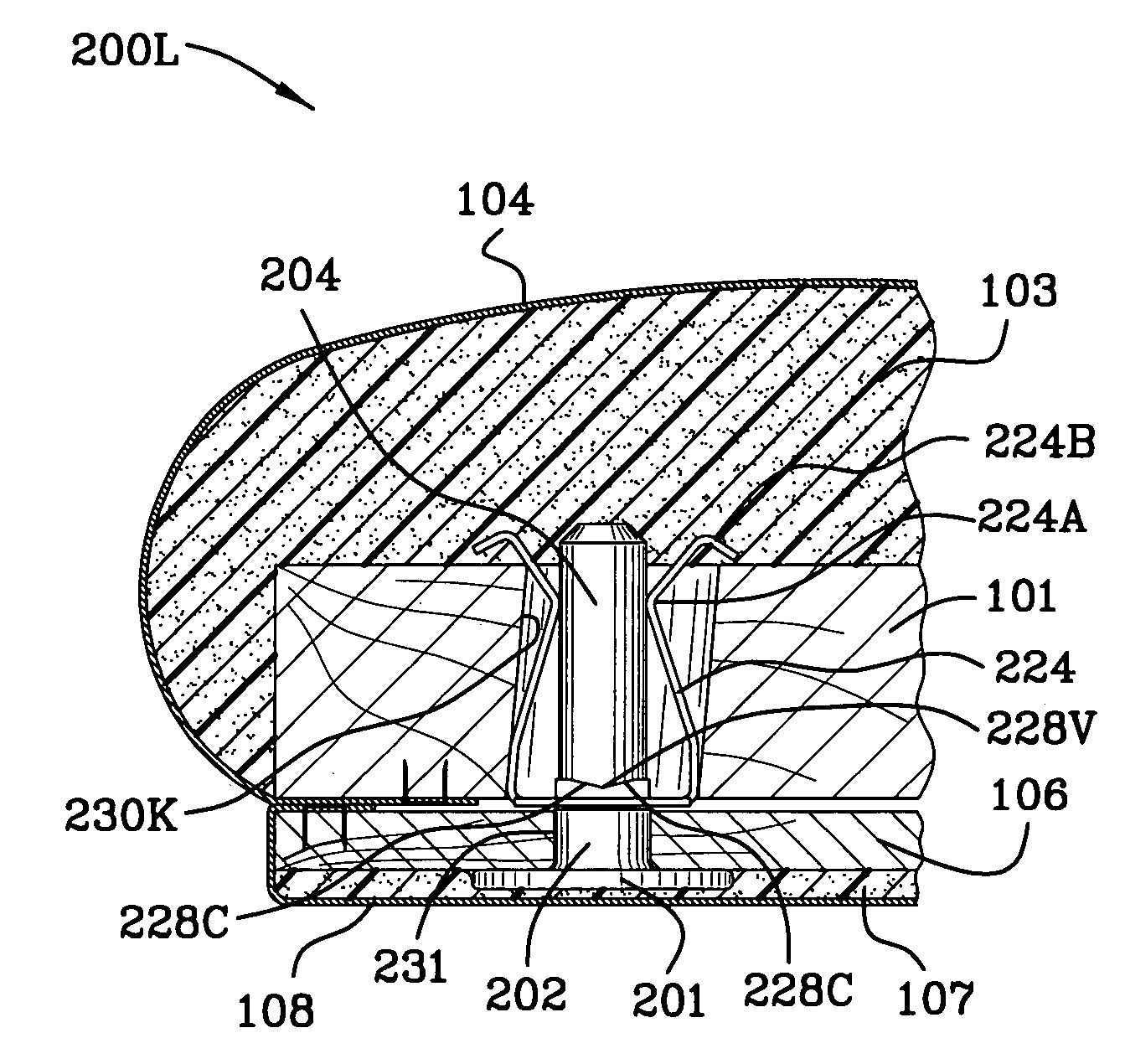
[0015]A connector for securing first and second substrates together, comprising: an outer fastener and an inner fastener is disclosed and claimed. The outer fastener comprises a dowel shaped stud. The inner fastener comprises a flange and a pair of clips. Each of the clips includes a first portion and a second portion. The flange is lanced and includes a punched out portion. The stud interengages the flange and the second portion of the pair of clips urges the clips away from each other and away from the stud. The outer fastener is pressed into the first substrate and the second portion of the clips is pressed into the second substrate. The second portion of the clips include a turned back portion and the turned back portion of the clip prevents removal of the inner fastener from the second substrate. The connector is tolerant of the misalignment of the inner and outer fasteners and the bores in which the fasteners reside.
[0021]It is an object of the instant invention to provide a connector which easily connects and which is difficult to disconnect.

Problems solved by technology

The contours make drilling of through-bores in the inner and outer backs difficult.
This induces failure in the prior art Christmas tree Easterners as described herein.
As such, alignment of the through bores is not always achieved creating a need for a fastener system which is capable of tolerating alignment faults.
In the furniture manufacturing assembly process the misalignment of the through bores in the outer and inner backs is a known problem which creates difficulties in the assembly of the outer back and the inner back together.
If the covering is leather or some other soft material, however, then the staples used to join the outer and the inner backs together tends to tear the leather or any other soft covering which may be used.

Method used


Image

  • Fastener and process for using same
  • Fastener and process for using same
  • Fastener and process for using same

Examples


Embodiment Construction

[0050]FIGS. 1-1F have been described above in connection with the Background of the Invention.

[0051]As used herein the female portion of the fastener is referred to as the portion which receives the male portion of the fastener. The outer fastener 200 as described herein is the male portion of the fastener (male fastener) and the inner fastener 238 as described herein is the female portion of the fastener (female fastener).

[0052]FIG. 2 is a plan view of the outer fastener 200 of the instant invention. FIG. 2A is an end view 200A of the outer fastener 200 of the instant invention. The outer fastener 200 includes flange 201 and reference numeral 201 A indicates the inner surface of flange 201 and reference numeral 201B indicates the outer surface of the flange 201. Inner surface 201 A of the flange 201 of the male fastener engages the outer back as illustrated in FIG. 2I. A shank extends from the flange and the shank includes a larger diametrical portion 202 and a smaller diametrical ...


PUM


Abstract

A connector for securing first and second substrates together, comprising: an outer fastener and an inner fastener is disclosed and claimed. The outer fastener comprises a dowel shaped stud. The inner fastener comprises a flange and a pair of clips. The pair of clips includes a first portion and a second portion. The flange is lanced and includes a punched out portion. The stud interengages the flange and the second portion of the pair of clips urges the clips away from each other and away from the stud. The outer fastener is pressed into the first substrate and the second portion of the clips is pressed into the second substrate. The second portion of the clips include a turned back portion and the turned back portion of the clip grip the second substrate preventing removal of the inner fastener from the second substrate. The connector is tolerant of the misalignment of the inner and outer fasteners and the bores in which the fasteners reside.

Description

FIELD OF THE INVENTION[0001]The invention is in the field of furniture fasteners.BACKGROUND OF THE INVENTION[0002]FIG. 1 is a partial cross-sectional view 100 of a prior art outer Christmas tree fastener 110, 111, 111A, 111B inserted into an outer back 106 in proximity with an aperture 102 in an inner back 101. Foam 103 is placed over inner back 101. Typically, inner back 101 is made of wood or it may be plastic in some instances. A covering 104, for example, which may be leather or some other material, is placed over foam 103 and is stapled 105 to the wood substrate 101 as shown. Stapling wraps the covering around the foam and secures the foam in place. Christmas tree fastener 110, 111 is typically made of plastic and includes a shank portion 111, 111A as illustrated in FIG. 1F. Shank portion 111, 111A is illustrated in FIG. 1 as being aligned with aperture or bore 102 in inner back 101. As used herein the terms “bore” and “through-bore” are used interchangeably.[0003]Head 110 of t...

Claims


Application Information

Patent Timeline
IPC IPC(8): F16B21/18
CPCF16B5/0642F16B5/0657F16B21/073F16B21/065Y10T403/1616Y10S411/97
Inventor SELLE, STEPHEN
Owner STAFAST PROD
Learn More