Rewinding machine with gluing device to glue the final edge of the log formed and relative winding method

a rewinding machine and gluing device technology, applied in the direction of web handling, thin material processing, article delivery, etc., can solve the problems of poor gluing quality, inability to achieve the performance currently required of these machines in terms of production speed and production flexibility, and the rewinding machine is only capable of reaching relatively low winding speed, so as to achieve accurate gluing of the final edge

Inactive Publication Date: 2009-04-28
FABIO PERINI SPA
View PDF26 Cites 14 Cited by
  • Summary
  • Abstract
  • Description
  • Claims
  • Application Information

AI Technical Summary

Benefits of technology

[0012]The object of the present invention is to provide a method and a rewinding machine for producing logs of wound web material, which make it possible to accurately glue the final edge of the logs or logs, without requiring a gluing unit downstream of the rewinding machine or incorporated in it.
[0013]According to a particular aspect a further object of the present invention is to provide a method and a machine that make it possible to attain high performances in terms of production flexibility.

Problems solved by technology

With a layout of this type it is not possible to attain the performances currently required of these machines in terms of production speed and production flexibility.
Moreover, the quality of gluing is poor, as the glue is distributed according to arcs of circumference, rather than along a line parallel to the axis of the log, which are also spaced at a considerable distance from one another in an axial direction.
Nonetheless, owing to its design and to the layout of the gluing unit, this rewinding machine is only capable of reaching relatively low winding speeds.
The first glue is applied with a system of nozzles, which have some drawbacks, in particular due to the fact that, especially at high production speeds, they are unable to apply the glue in a precise and definite way.
The glue applied to glue the final edge of each log is not distributed optimally, especially when the production speed (that is the feed speed of the web material) is high.
This poses a considerable problem, in particular when producing rolls of toilet tissue or the like with a small diameter, especially for domestic use where the accuracy of gluing the free edge of the log is essential.

Method used


Image

  • Rewinding machine with gluing device to glue the final edge of the log formed and relative winding method
  • Rewinding machine with gluing device to glue the final edge of the log formed and relative winding method
  • Rewinding machine with gluing device to glue the final edge of the log formed and relative winding method

Examples


Embodiment Construction

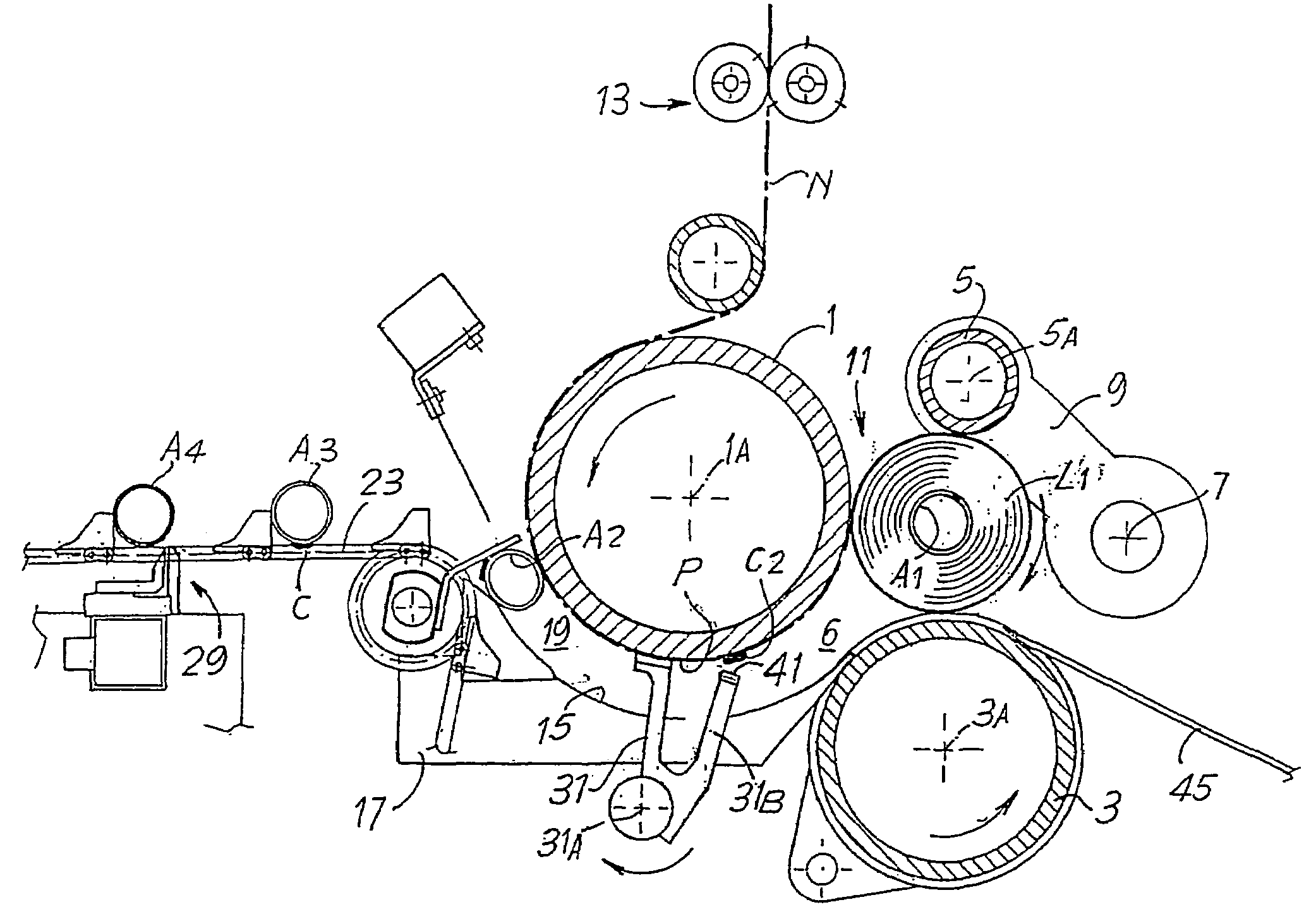
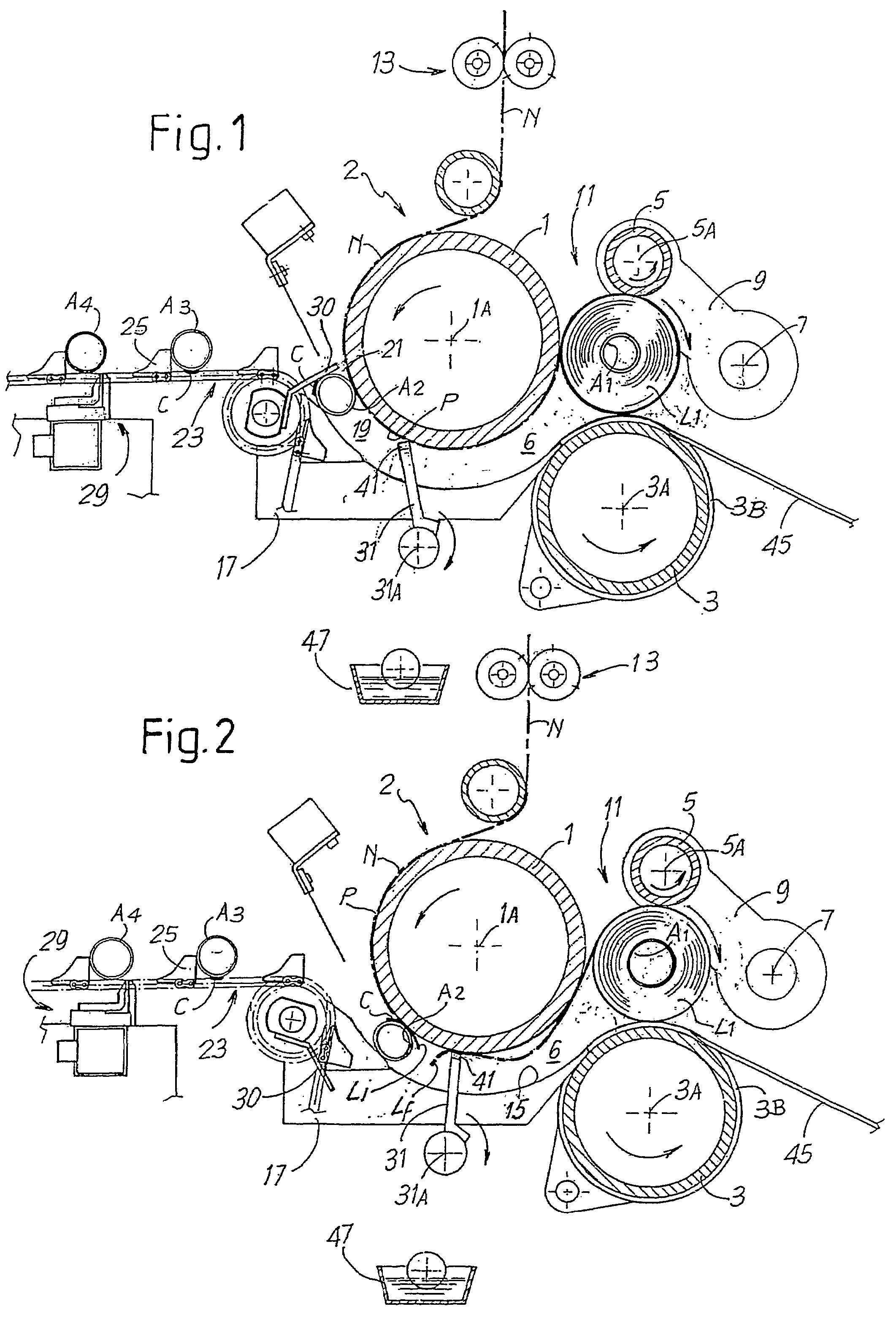
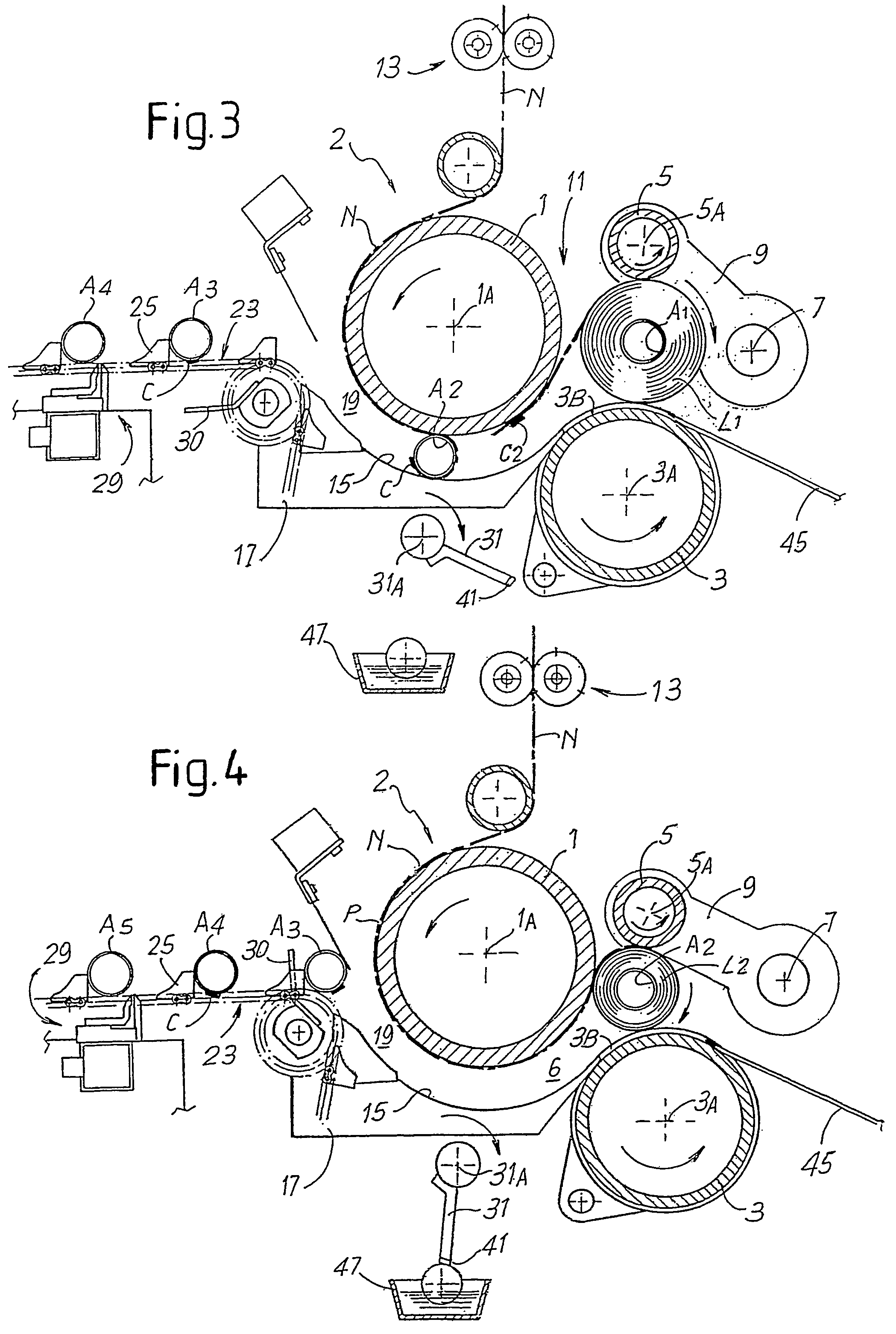
[0038]FIGS. 1 to 4 show, limited to its principal elements, a first embodiment of a rewinding machine according to the invention in four distinct positions during the winding cycle.

[0039]The rewinding machine, indicated as a whole with 2, comprises a first winding roller 1, rotating around an axis 1A, a second winding roller 3, rotating around a second axis 3A parallel to the axis 1A, and a third winding roller 5, rotating around an axis 5A parallel to the axes 1A and 3A; The winding roller 5 is supported by oscillating arms 9 hinged around an oscillation axis 7.

[0040]The three winding rollers 1, 3 and 5 define a winding cradle 11 inside which, in the position shown in FIG. 1, a first log L1 of web material is found in the final winding phase.

[0041]A nip 6 is defined between the winding rollers 1 and 3 through which the web material N passes, which is wound around a tubular core A1 to form the log L1. The web material N is fed around the first winding roller 1 and, before reaching i...


PUM

PropertyMeasurementUnit
speedaaaaaaaaaa
adhesiveaaaaaaaaaa
diameteraaaaaaaaaa

Abstract

The rewinding machine comprises: winding elements (1, 3, 5) to wind the web material (N) and form the logs (L1, L2); at least a first glue dispenser (31B) to apply a first glue (C2) to a portion of said web material, in proximity to a severing line, along which the web material is severed upon termination of winding a log. The first glue dispenser comprises a mechanical element (31B) that touches the web material (N) upon termination of winding each log (L1, L2), to transfer the first glue to the web material (N).

Description

TECHNICAL FIELD[0001]The present invention relates to a method for producing logs of web material, for example rolls of toilet tissue, kitchen towels or the like.[0002]The invention also relates to a rewinding or winding machine for forming logs destined to produce small rolls of wound web material.[0003]The invention relates in particular, although not exclusively, to rewinding machines of the peripheral type, i.e. in which the log is formed in a winding cradle in contact with moving elements that transmit rotatory movement to the log through surface contact.STATE OF THE ART[0004]Currently, to produce rolls of toilet tissue, rolls of kitchen towels or similar products a web material is unwound from one or more parent reels of large diameter, coming directly from the paper mill, and predetermined quantities of web material are rewound on tubular winding cores to obtain logs of a length equivalent to the length of the parent reel but with a minor diameter, equivalent to the diameter ...

Claims


Application Information

Patent Timeline
Patent Type & Authority Patents(United States)
IPC IPC(8): B65H35/10B65H19/29B65H19/26
CPCB65H19/267B65H19/29B65H2301/41421B65H2301/41441B65H2301/414421B65H2301/414422B65H2301/41812B65H2301/5152B65H2408/235B65H2513/104B65H2513/10
Inventor GELLI, MAUROMADDALENI, ROMANO
Owner FABIO PERINI SPA
Why Eureka
Try Eureka