
Mower with an unfolding and folding device that includes a tilting element, a link rod, and a hydraulic jack

a technology of unfolding and folding device and mower, which is applied in the field of agricultural machinery, can solve the problems of limiting the size of the mower in the transport configuration, the inability to adjust the height of the mower, and the machine that has very long bars

Inactive Publication Date: 2009-04-28
KUHN SA
View PDF10 Cites 11 Cited by
  • Summary
  • Abstract
  • Description
  • Claims
  • Application Information

AI Technical Summary

Benefits of technology

[0020]An articulation of the cutter bar such as this, using a double-acting jack according to the invention, displays numerous advantages:
[0021]The cutter assembly is more lightweight and less expensive to manufacture because just one double-acting jack can be used.
[0022]The mechanism allows an easy switch from a work configuration to a maneuvering configuration or vice versa.
[0023]Each configuration can have safety measures that prevent unwanted movements of the cutter bar.
[0024]It is advantageously possible to have an additional safety measure, in the transport configuration, when the cutter bar is lying beyond the vertical, in order to compensate for the failure of the tractor's hydraulic circuit and therefore prevent the tool from falling down and becoming damaged in such an eventuality.

Problems solved by technology

With long cutter bars, the problem of the size of the mower in transport configuration arises.
This solution is suited to machines with cutter bars of medium size, but not for machines that have very long bars, because their center of gravity becomes so far away from the tractor.
For longer cutter bars, folding the bar upwards, vertically, has proved to be an attractive solution, although here again, the permissible size for transport has proved limiting and new solutions have been investigated.
The use of two single-acting jacks between the supporting structure and the cutter bar entails a bearing frame and a complex arrangement of jacks in order to effect the various movements of the cutter bar with the protector; this solution is expensive and not very functional.
The articulations that allow the cutter bar of mowers to be unfolded and folded additionally present safety problems in the various operating configurations.
There is therefore a problem as regards the functionality and the folding—unfolding of the cutter bar using articulations that are inexpensive but have the safety measures in place that are necessary for all the configurations: transport, work or maneuvering.

Method used


Image

  • Mower with an unfolding and folding device that includes a tilting element, a link rod, and a hydraulic jack
  • Mower with an unfolding and folding device that includes a tilting element, a link rod, and a hydraulic jack
  • Mower with an unfolding and folding device that includes a tilting element, a link rod, and a hydraulic jack

Examples


Embodiment Construction

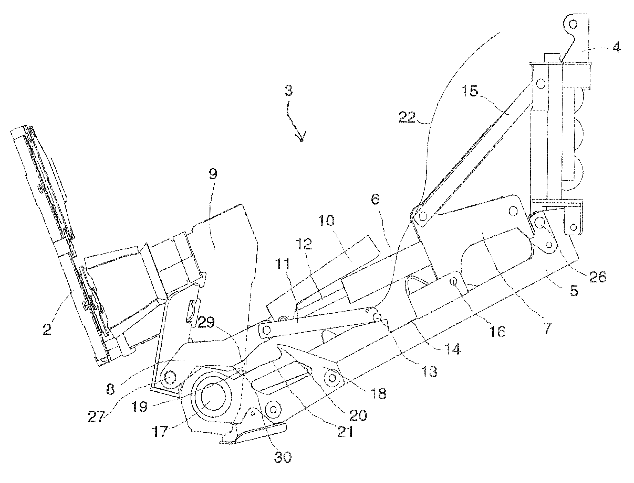
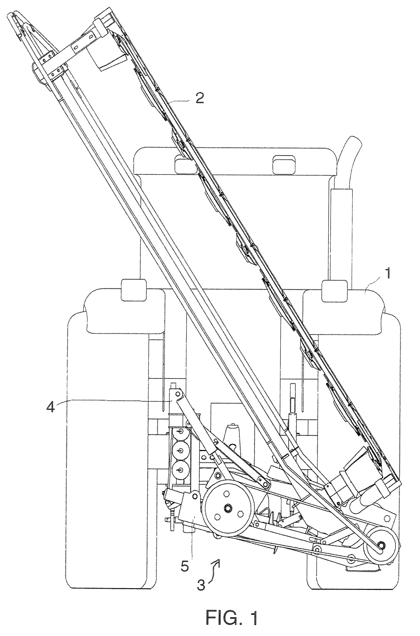
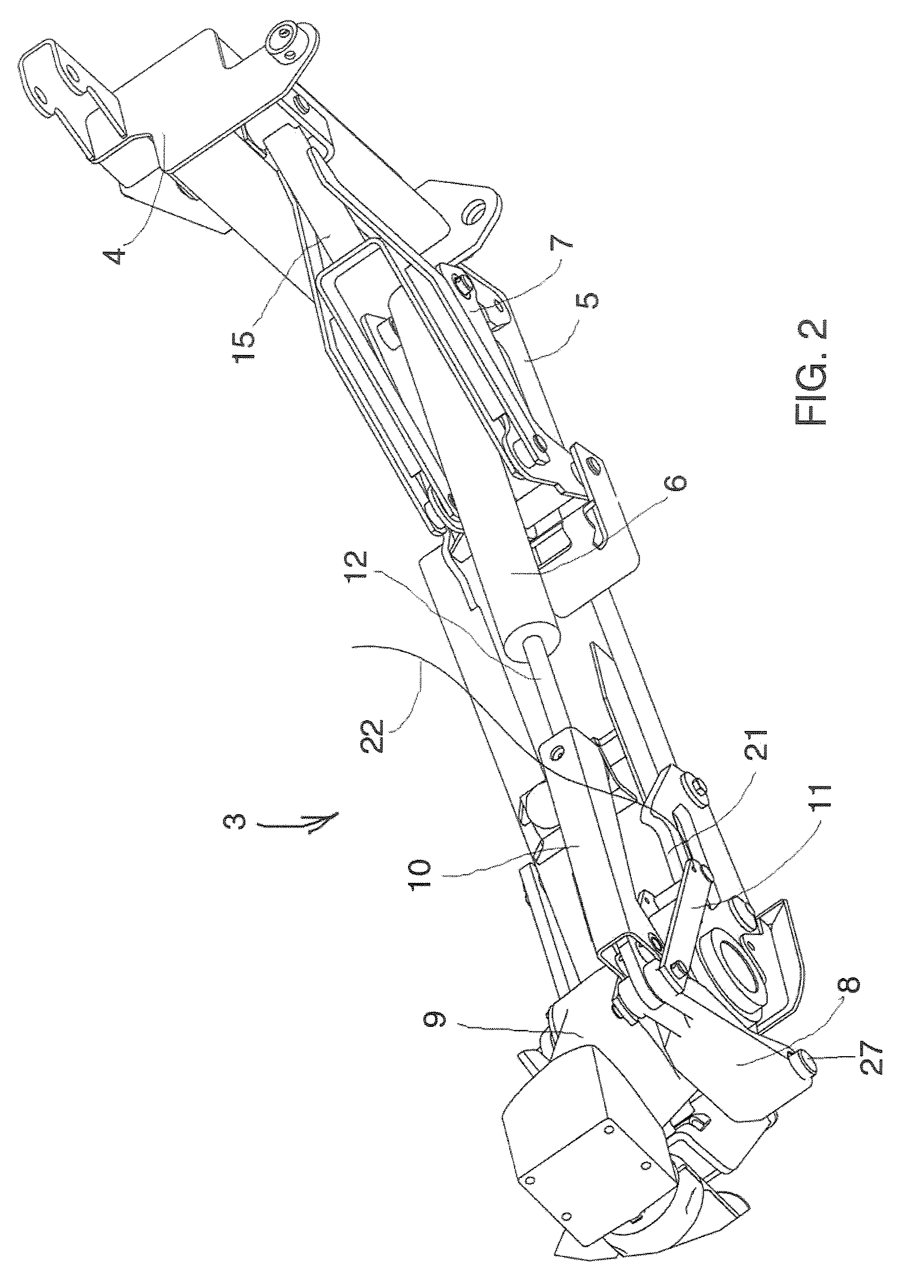
[0035]The mower according to the invention has a cutter bar 2 formed of a casing of elongate shape bearing several rotary cutting tools 25. These can be rotationally driven in a way known per se off a tractor. In FIGS. 2 to 11 the transmission system for operating the cutting tools 25 and the various protective means of the mower have not been depicted, in order to make the invention easier to understand.

[0036]The cutter bar 2 comprises a drive transmission box 9 which is connected by a substantially horizontal articulation 17 to a support beam 5. The latter is also articulated via a substantially horizontal axis 26 to a supporting structure 4 equipped in a way known per se with a three-point hitching frame for coupling to the lift system of the tractor.

[0037]FIG. 1 illustrates the position of the mower in the transport configuration, that is to say folded at the rear of the tractor 1, in a diagonal plane. The cutter bar 2 is pivoted at substantially 125° with respect to the horizon...


PUM


Abstract

A mower includes a supporting structure that can be coupled to a tractor and bears a support beam to which there is articulated a cutter bar that can be brought from a work configuration into at least one transport configuration and vice versa using an unfolding and folding device. The unfolding and folding device includes a tilting element connected to the support beam and to the supporting structure, a link rod connected to the cutter bar, a double-acting jack positioned between the tilting element and the link rod.

Description

BACKGROUND OF THE INVENTION[0001]1. Field of the Invention[0002]The invention relates to the field of agricultural machinery, more particularly that of mowers.[0003]2. Discussion of the Background[0004]Mowers are known from several documents, especially patents EP 839 443, EP 809 928 or FR 2 635 433 in the name of the Applicant Company. These machines are fixed to the lift system of a tractor using a supporting structure with a three-point hitching frame for coupling.[0005]In the transport configuration, the cutter bar is folded behind the tractor in order to occupy a minimum amount of space to allow the vehicle to move around on the road network.[0006]In the work configuration, the cutter bar is deployed to the side of the tractor so as to mow the plants.[0007]For reasons of maximum productivity, the use of bars supporting a great many cutting tools is desirable, that is to say a cutter bar that is as long as is technically feasible.[0008]With long cutter bars, the problem of the s...

Claims


Application Information

Patent Timeline
IPC IPC(8): A01D34/83
CPCA01D34/661
Inventor WOLFF, MICHEL
Owner KUHN SA
Learn More