
Video display appliance and signal processing apparatus detachably connected thereto

a technology for video display and signal processing, which is applied in the direction of television systems, instruments, color signal processing circuits, etc., can solve the problems of increased weight and weight of products, increased weight and manufacturing costs of products, and complicated product design, so as to minimize the influence of nois

Inactive Publication Date: 2009-04-21
LG ELECTRONICS INC
View PDF8 Cites 0 Cited by
  • Summary
  • Abstract
  • Description
  • Claims
  • Application Information

AI Technical Summary

Benefits of technology

The present invention is a video display appliance with a separated signal processing unit that receives a video signal from an external signal source. This appliance minimizes the impact of noise and improves the quality of the video display. The signal processing apparatus is detachably connected to the video display appliance and can be easily connected and disconnected. The appliance includes an interface for receiving the video signal and a detection signal indicating the connection state of the signal processing apparatus. The signal processing apparatus includes a video signal processing unit, a video decoder, a deinterlacer, a scaler, a microcomputer, a driving circuit, and a detecting circuit. The video display appliance can display a video signal from an external source and the signal processing apparatus can be easily connected and disconnected. The technical effects of this invention include improved video quality, reduced noise interference, and improved signal processing.

Problems solved by technology

Due to these functions that have been previously unused in the past, the dimension and weight of the product have increased.
However, due to various jacks and signal processing units for processing the various input signals, the design of the product is more complicated, and the weight and manufacturing cost of the product are significantly increased.

Method used


Image

  • Video display appliance and signal processing apparatus detachably connected thereto
  • Video display appliance and signal processing apparatus detachably connected thereto
  • Video display appliance and signal processing apparatus detachably connected thereto

Examples


first embodiment

[0043

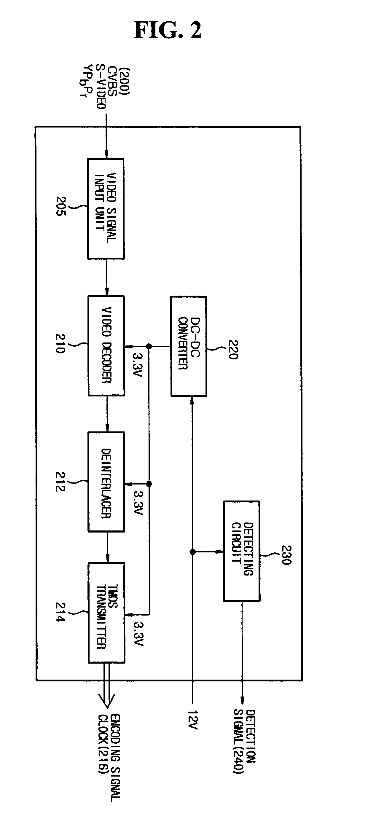
[0044]The construction and operation of a video display appliance from which a signal processing apparatus is separated, according to a first preferred embodiment of the present invention, will now be described with reference to FIGS. 2 to 4. FIG. 2 is a block diagram of a video signal processing apparatus separated from the video display appliance according to an embodiment of the present invention. FIG. 3 is a block diagram of a PC signal processing apparatus separated from the video display appliance according to an embodiment of the present invention. FIG. 4 is a block diagram of a video display appliance from which a video signal and a PC signal processing apparatus are separated. The detachable video display appliance according to the present embodiment may be connected to a desired signal processing apparatus, such as the video signal processing apparatus or the PC signal processing apparatus, by use of a communication cable.

[0045]The construction and operation of the vi...

second embodiment

[0065

[0066]The construction and operation of a video display appliance according to a second preferred embodiment of the present invention, and a video signal processing apparatus or PC signal processing apparatus which is selectively detached to the video display appliance will now be described in detail with reference to FIGS. 5 to 8.

[0067]FIG. 5 is a block diagram of the PC signal processing apparatus detachable to the video display appliance according to the present invention.

[0068]As shown in FIG. 5, the PC signal processing apparatus includes a PC signal input unit 405, a DVI signal input unit 407, an A / D converter 420, a TMDS transmitter 430, a DC-DC converter 440 and a detecting circuit 450.

[0069]The PC signal input unit 405 receives a video signal and a control signal from the external PC in analog form. The A / D converter 420 converts the signals inputted from the PC signal input unit 405 into digital signals to output the converted signals to the video display appliance. A...

third embodiment

[0087

[0088]The construction and operation of a signal processing apparatus capable of being connected to a detachable video display appliance according to a third preferred embodiment of the present invention via a cable will now be described in detail with reference to FIG. 9.

[0089]The signal processing apparatus according to the embodiment is provided by integrally forming the video signal processing apparatus and the PC signal processing apparatus, and is connected to the detachable video display appliance via a communication cable.

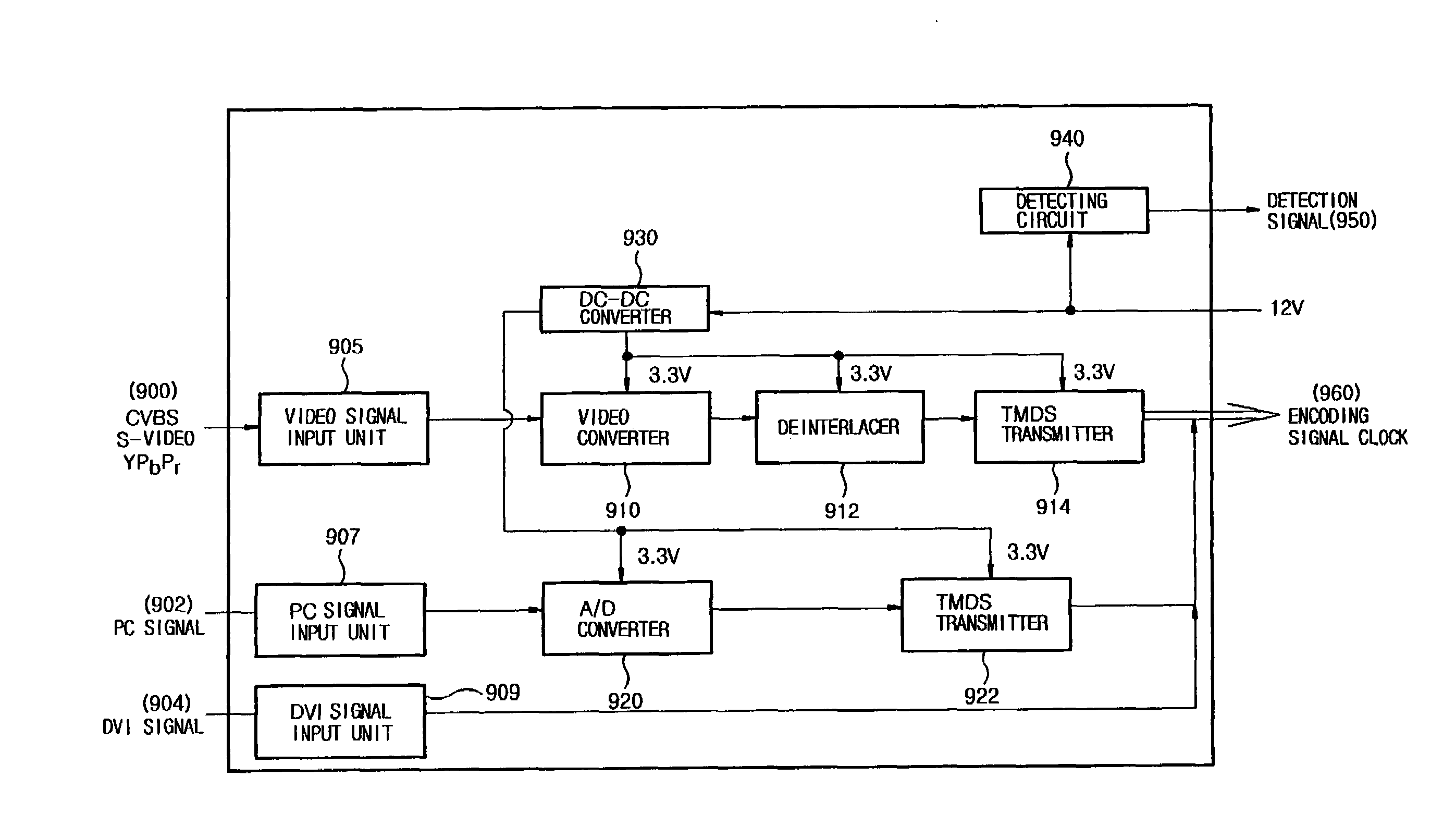
[0090]FIG. 9 is a block diagram of a signal processing apparatus according to the present invention. The detachable video display appliance to which the signal processing apparatus is connected has the same construction as that shown in FIG. 4.

[0091]Referring to FIG. 9, the signal processing apparatus according to the present invention includes a video signal input unit 905 receiving a video signal 900, such as CVBS, S-video or YPbPr, a PC signal input...


PUM


Abstract

Disclosed is a video display appliance from which a video signal processing unit and a PC signal processing unit are separated and to which the separated signal processing units are detachably connected or connected by a communication cable. The video display appliance includes an interface receiving a digital video signal to be displayed on the panel and a detection signal indicating a connection state of the signal processing apparatus from the signal processing apparatus, a microcomputer for controlling operation of the video display appliance according to the detection signal transmitted from the interface, a scaler for converting a video signal transmitted from the interface to match a resolution of the panel under the control of the microcomputer, and a driving circuit for driving the panel by using the video signal inputted from the scaler. The signal processing apparatus can be detachably connected to the video display appliance.

Description

BACKGROUND OF THE INVENTION[0001]1. Field of the Invention[0002]The present invention relates to a video display appliance with a separated signal processing unit receiving a video signal inputted from an external signal source, and more particularly, to a video display appliance from which a video signal processing unit and a PC signal processing unit are separated and to which the separated signal processing units are detachably connected or connected by a communication cable.[0003]2. Description of the Related Art[0004]Due to the recent developments to the field of the video display appliances, such as LCD projectors, several products providing new technology and various functions have been released in the market. Due to these functions that have been previously unused in the past, the dimension and weight of the product have increased.[0005]The construction of a conventional LCD video display appliance will now be described with reference to FIG. 1.[0006]As shown in FIG. 1, the ...

Claims


Application Information

Patent Timeline
Patent Type & Authority Patents(United States)
IPC IPC(8): G09G5/00H04N5/44H04N5/74H04N9/64
CPCG09G5/006H04N5/74H04N9/641H04N7/012
Inventor LEE, KWANG MIN
Owner LG ELECTRONICS INC
Learn More