
Method and apparatus for dynamically modifying a computer system configuration

a computer system and configuration technology, applied in the field of method and apparatus for dynamically modifying a computer system configuration, can solve the problems of significant problems for applications executing on the host computer, overwriting the wrong data, and inaccessible logical volumes

Inactive Publication Date: 2009-04-14
EMC IP HLDG CO LLC
View PDF48 Cites 37 Cited by
  • Summary
  • Abstract
  • Description
  • Claims
  • Application Information

AI Technical Summary

Benefits of technology

Enables transparent and automatic adaptation to system configuration changes, preventing data access errors and reducing the need for manual intervention by dynamically updating mapping information to maintain accurate logical volume access.

Problems solved by technology

This can cause problems when changes are made to the physical configuration of the computer system.
It should be appreciated that this can cause significant problems for applications executing on the host computer 1.
Therefore, when performing reads, the application program will actually read the wrong data, and when performing writes, the application program will be overwriting the wrong data in the storage system 3.
This can result in the wrong data being accessed for a read or write, or can result in a logical volume becoming inaccessible to an application program which is not capable of accessing the logical volume via its new device identifier.
Conventional computer systems do not provide any technique for automatically detecting a change in the system configuration which can lead to the above-described problems.
In addition, even if a system reconfiguration is manually detected in this manner, conventional systems do not provide any technique for dynamically addressing such system configuration changes.

Method used


Image

  • Method and apparatus for dynamically modifying a computer system configuration
  • Method and apparatus for dynamically modifying a computer system configuration
  • Method and apparatus for dynamically modifying a computer system configuration

Examples


Embodiment Construction

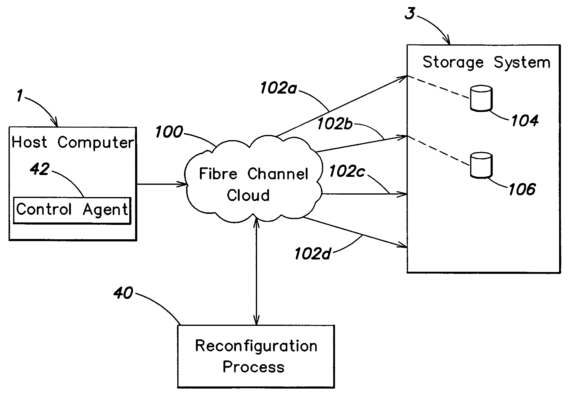
[0034]In accordance with one illustrative embodiment of the present invention, a method and apparatus is provided for dynamically reconfiguring a computer system without requiring rebooting or reinitializing of the computer system. This aspect of the present invention can be used, for example, in connection with a computer system resource (e.g., the host computer 1 of FIG. 1) that accesses other system components (e.g., logical volumes in the storage system of FIG. 1), such that if the computer system is reconfigured so that there is a change in the physical path through which a particular logical volume is accessed by the host computer, the host computer can be dynamically reconfigured to recognize the change without requiring reinitialization of the host computer.

[0035]In accordance with another illustrative embodiment of the present invention, a computer system resource (e.g., the host computer 1 of FIG. 1) that accesses other system components (e.g., the storage system of FIG. 1...


PUM


Abstract

One embodiment is directed to a method and apparatus for modifying a configuration of a computer system including a host computer and at least one computer system resource accessible to at least one application program executing on the host computer. The computer system is dynamically reconfigured, without reinitializing the host computer or the application program, to alter a manner in which the at least one application program accesses the at least one computer system resource. Another embodiment is directed to a method and apparatus for responding to changes in a configuration of the computer system impacting a manner in which the at least one computer system resource is accessed by the host computer. Information relating to a first configuration of the computer system at a first point in time is stored, the first configuration relating to a first manner of accessing the at least one computer system resource by the host computer. A second configuration of the computer system at a second point in time is determined, the second configuration relating to a second manner of accessing the at least one computer system resource by the host computer. The second configuration of the computer system is compared with the first configuration to determine whether the second configuration differs from the first configuration. When it is determined that the second configuration differs from the first configuration, the second manner of accessing the at least one computer system resource by the host computer is determined.

Description

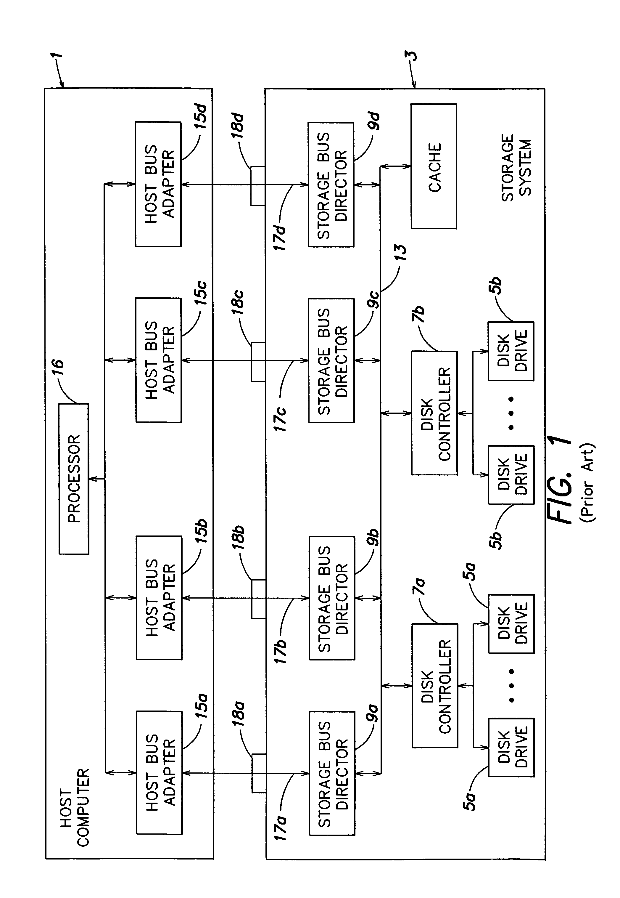
CROSS-REFERENCE TO RELATED APPLICATION[0001]This application is a continuation of U.S. application Ser. No. 09 / 295,718, filed Apr. 21, 1999 (now U.S. Pat. No. 6,931,440) which is incorporated herein by reference.FIELD OF THE INVENTION[0002]The present invention is directed to a method and apparatus for dynamically modifying a computer system configuration without reinitializing the computer system.DESCRIPTION OF THE RELATED ART[0003]Many computer systems include one or more host computers and one or more system resources that are accessible thereby. An example of such a computer system is shown in FIG. 1, and includes a host computer 1 and a storage system 3 that serves as a system resource accessible by the host computer 1. The storage system 3 includes a plurality of storage devices on which data are stored. In the exemplary system shown in FIG. 1, the storage system 3 includes a plurality of disk drives 5a and 5b and a plurality of disk controllers 7a-7b that respectively control...

Claims


Application Information

Patent Timeline
Patent Type & Authority Patents(United States)
IPC IPC(8): G06F15/177G06F3/06G06F9/00G06F15/16
CPCG06F3/0605G06F3/0629G06F3/0653G06F3/0683G06F9/4411
Inventor BLUMENAU, STEVENCOHEN, STEVEN
Owner EMC IP HLDG CO LLC
Learn More