
Portable hand tool

a hand tool and portable technology, applied in the field of hand tools, can solve the problems of disadvantageous time-consuming and unsatisfactory devices, and achieve the effects of quick and easy movement of shafts, quick and easy adjustment, and quick and easy achievemen

Active Publication Date: 2009-04-14
WESTLAKE ROYAL BUILDING PROD INC
View PDF7 Cites 0 Cited by
  • Summary
  • Abstract
  • Description
  • Claims
  • Application Information

AI Technical Summary

Benefits of technology

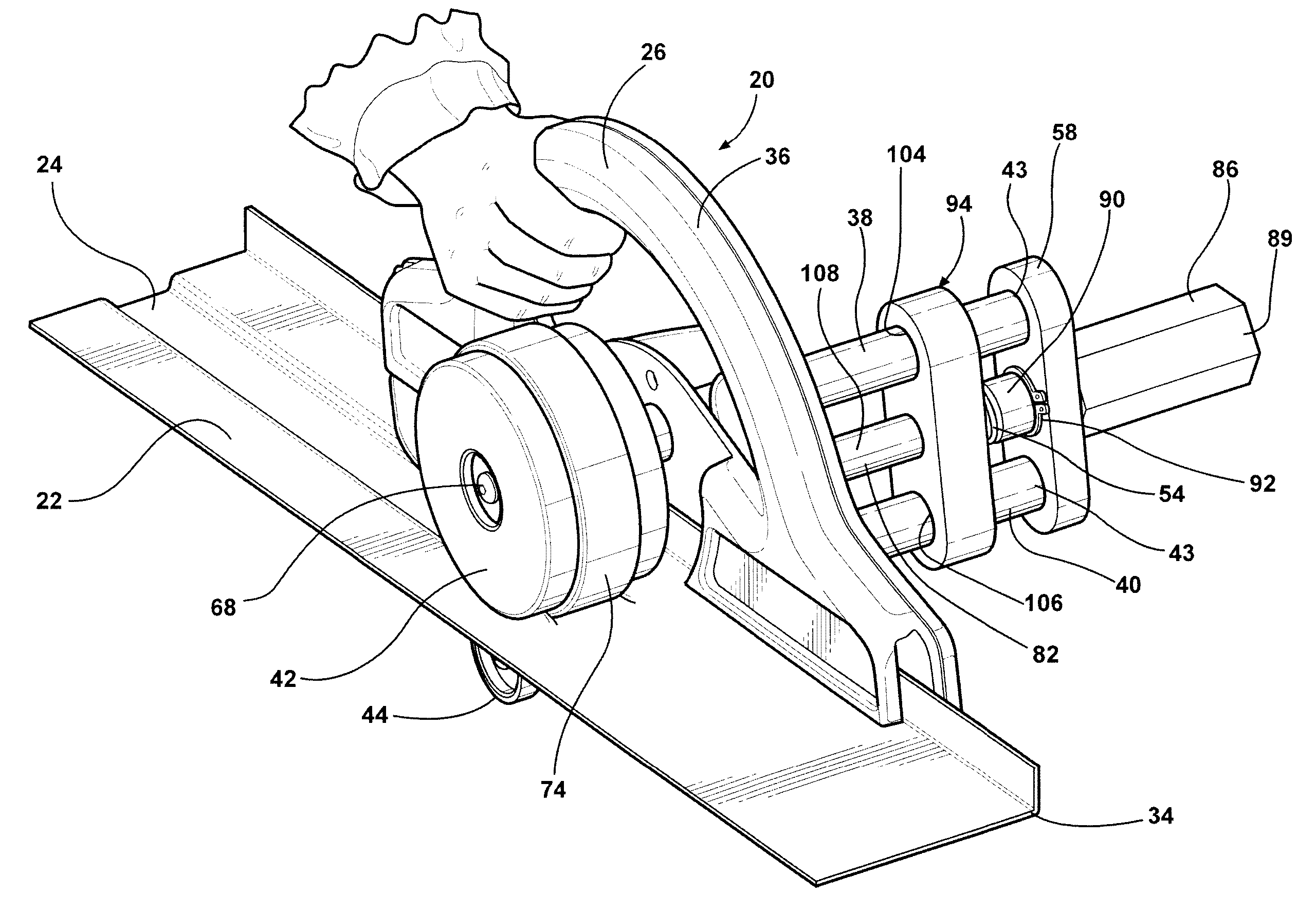
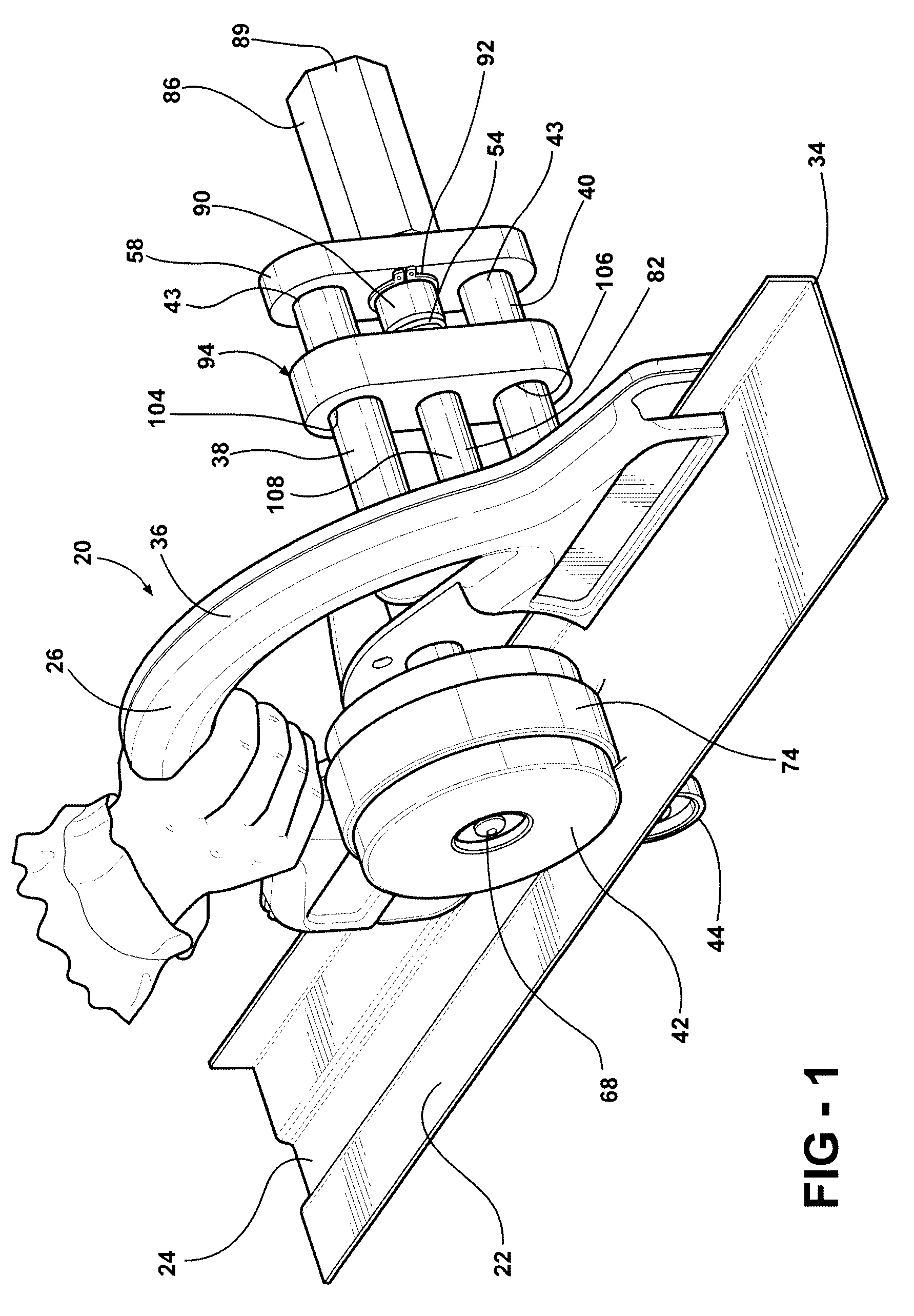
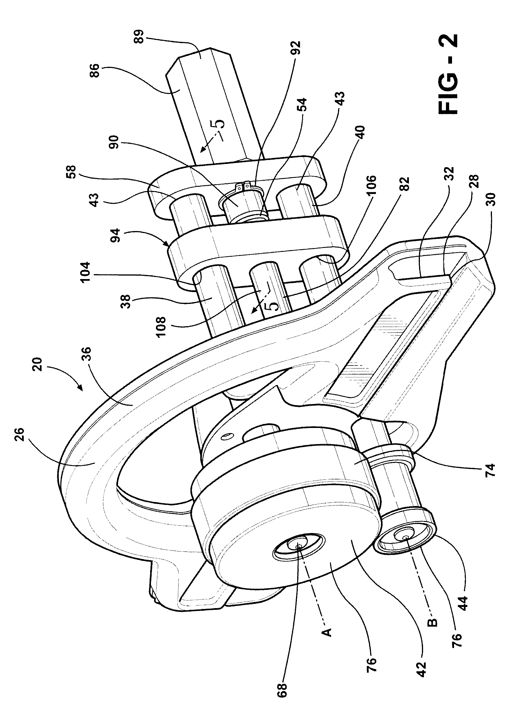
[0012]Accordingly, the coupling device is moved between the engaged and disengaged positions to respectively lock and unlock the rollers relative to the frame. When in the disengaged position, the shafts slide relative to the frame to quickly and easily move the shafts between adjustment positions. When the appropriate adjustment position is located, the coupling device is moved to the engaged position to lock the shafts in place relative to the frame thereby locking the lateral position of the rollers relative to the frame. As such, the location of the rollers relative to the frame is quickly and easily adjusted regardless of the magnitude of adjustment that is required. In other words, an adjustment requiring movement of the rollers over a relatively large distance is quickly and easily achieved by moving the coupling device to the disengaged position and sliding the shafts and the rollers relative the frame.

Problems solved by technology

Such an adjustment that requires several turns of the adjustment device is ergonomically unsatisfactory and is disadvantageously time consuming.

Method used


Image

  • Portable hand tool
  • Portable hand tool
  • Portable hand tool

Examples


Embodiment Construction

[0019]Referring to the Figures, wherein like numerals indicate like parts throughout the several views, a portable hand tool 20 is generally shown. As shown in FIG. 1, the portable hand tool 20 deforms a portion of a sheet 22 of material. The portable hand tool 20 of this type may be referred to by those skilled in the art as a brake. For example, the material is a metal such as steel or aluminum and may be used for siding a building such as a commercial or residential building. Specifically, the sheet 22 of material may be formed into a siding panel at the site of the building prior to installation onto the building.

[0020]The portable hand tool 20 is used to strengthen and reinforce the siding panel. Specifically, portable hand tool 20 is used to form a groove 24 in the sheet 22 of material. The groove 24 reinforces the sheet 22 of material to reduce the tendency of the sheet 22 of material to bend. The groove 24 also eliminates rippling that occurs when a nail is driven through th...


PUM

PropertyMeasurementUnit
movementaaaaaaaaaa
compressaaaaaaaaaa
diameteraaaaaaaaaa

Abstract

A portable hand tool includes a frame for guiding a sheet of material, e.g., sheet metal. A pair of shafts are spaced from each other and are selectively slideable relative to the frame to define a plurality of adjustment positions. A pair of rollers are respectively mounted to the shafts for deforming the sheet of material between the rollers. An adjustment rod is mounted to and extends outwardly from the frame. A support interconnects the shafts and an adjustment device is rotatably engaged with the support. A coupling device is disposed about the adjustment rod and is moveable between an engaged position and a disengaged position. In the engaged position, the coupling device couples the adjustment rod and the adjustment device to lock the shafts and rollers laterally relative to the frame. In the disengaged position, the shafts and rollers are slideable relative to the frame between the adjustment positions.

Description

CROSS-REFERENCE TO RELATED APPLICATIONS[0001]The subject patent application claims priority to and all the benefits of U.S. Provisional Patent Application Ser. No. 60 / 800,759 which was filed on May 16, 2006, the entire specification of which is expressly incorporated herein by reference.BACKGROUND OF THE INVENTION[0002]1. Field of the Invention[0003]The present invention relates to a portable hand tool, and more specifically a portable hand tool used for deforming a sheet of material such as sheet metal.[0004]2. Description of the Related Art[0005]Various portable hand tools are known in the art for deforming a portion of a sheet of material, e.g., sheet metal. One application for the portable hand tool is for deforming a groove into the sheet of material to form a siding panel for a building. The portable hand tool is sized such that it is easily transported to a site of the building so that the sheet of material is deformed at the site of the building prior to installation onto th...

Claims


Application Information

Patent Timeline
Patent Type & Authority Patents(United States)
IPC IPC(8): B21D7/02
CPCB21D17/04Y10T83/68
Inventor ROUSH, TIMOTHY J.CLARK, MICHAEL C.
Owner WESTLAKE ROYAL BUILDING PROD INC
Learn More