
Satellite equipment mounting panel

Active Publication Date: 2009-04-07
LOCKHEED MARTIN CORP
View PDF5 Cites 36 Cited by
  • Summary
  • Abstract
  • Description
  • Claims
  • Application Information

AI Technical Summary

Benefits of technology

[0003]The subject matter disclosed herein solves these problems by providing a satellite payload structure that includes vertically-oriented equipment mounting panels. By vertically stacking the equipment mounting panels, electrical and electronic equipment may be positioned adjacent to one or more elongated propellant tanks while still complying with size constraints imposed by other portions of the satellite and the satellite launch vehicle. Along with accommodating more electrical and electronic equipment, more equipment is located proximate to thermal radiators that interface with the lower temperature environment of deep space, thereby increasing heat dissipation capacity and efficiency.

Problems solved by technology

For example, fuel storage devices such as propellant tanks may require a substantial portion of satellite real estate.
While these horizontally-stacked panels may provide appropriate equipment space for this propellant tank design, for other propellant tank designs, the size constraints of a launch vehicle may not be satisfied.
Additionally, by horizontally-stacking the equipment mounting panels, heat generated by the electrical and electronic equipment populating the mounting panels may not be efficiently dissipated to hold the equipment within allowable temperature ranges.

Method used


Image

  • Satellite equipment mounting panel
  • Satellite equipment mounting panel
  • Satellite equipment mounting panel

Examples


Embodiment Construction

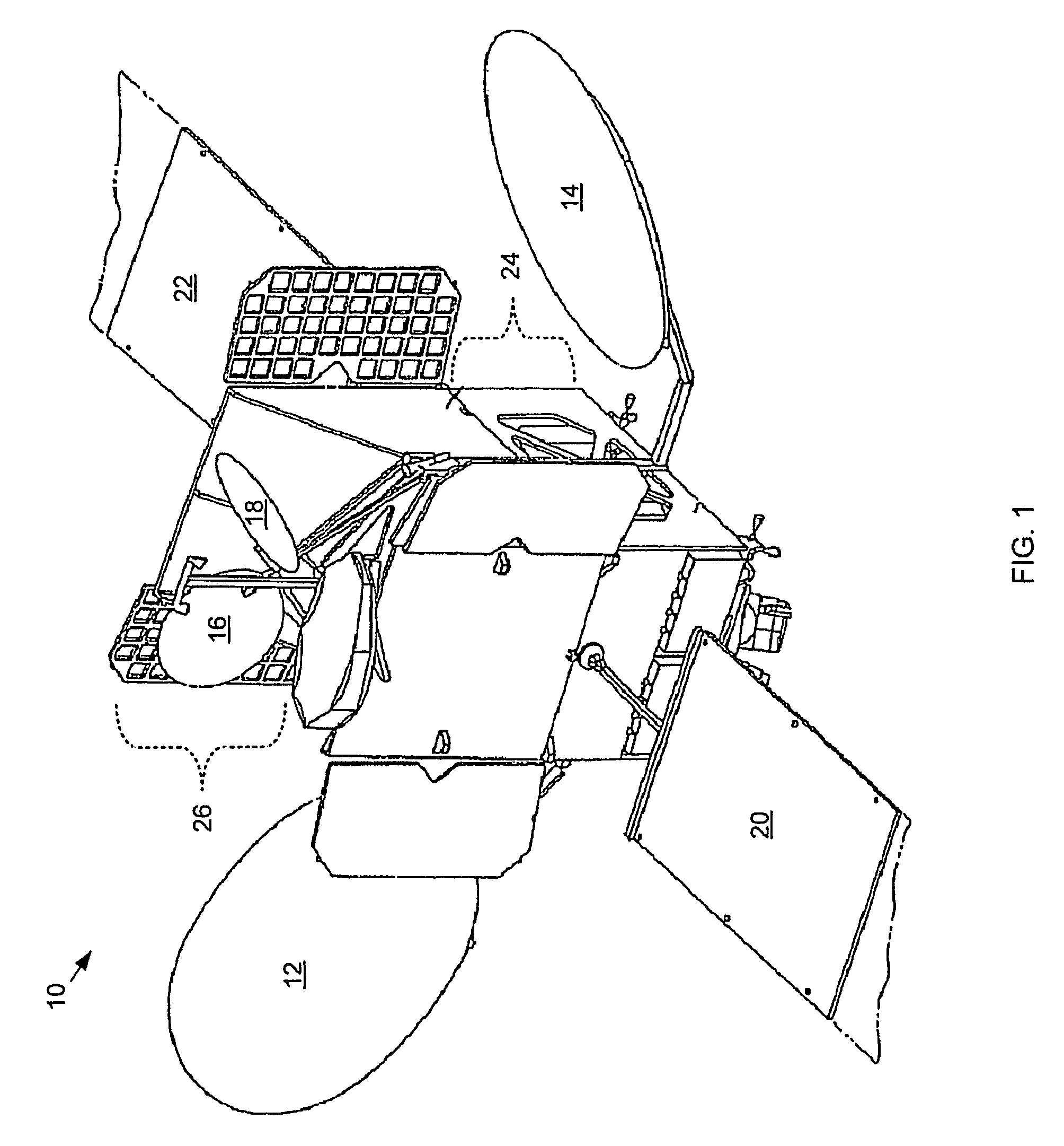
[0013]Referring to FIG. 1, a satellite 10 is shown in a deployed position and includes four reflector dish antennas 12, 14, 16, 18 for transmitting and / or receiving radio frequency (RF) signals to or from other communication sites (e.g., stationary sites, mobile sites, etc.). To provide power for the communication operations, satellite 10 also includes two solar arrays 20, 22 (partially presented in the figure) for converting sunlight into electrical energy that may be stored in batteries on-board the satellite. Typically, solar arrays 20 and 22 are oriented such that the sun is substantially normal to the respective faces of the arrays. Additionally, a fuel storage module 24 is located in the lower portion of satellite 10. Typically fuel storage module 24 includes one or more propellant tanks that contain solid or fluid propellant. This propellant is used by engines on-board satellite 10 for deploying and adjusting the position or orientation of the satellite for variously assigned...


PUM


Abstract

A satellite payload structure includes one side that includes at least two equipment mounting panels. Each of the equipment mounting panels are oriented substantially parallel to each other such that when the satellite is deployed, each of the equipment mounting panels are substantially parallel to a vector pointing from the deployed location of the satellite to a point on the earth's surface. The point on the earth's surface is located vertically beneath the satellite such that the vector is substantially normal to the earth's surface.

Description

TECHNICAL FIELD[0001]This disclosure relates to panels for mounting equipment on-board a satellite and, more particularly, to orienting equipment mounting panels to efficiently utilize satellite payload space.BACKGROUND[0002]Satellites such as geostationary satellites carry hardware such as communication equipment and remote sensing equipment in a relatively small payload space. Along with the size constraints imposed on satellites by available space in launch vehicles, satellite payload space is also constrained by the other components included in the satellite. For example, fuel storage devices such as propellant tanks may require a substantial portion of satellite real estate. For such satellites, the design of the propellant tank or tanks may impinge upon the layout design of the satellite payload compartment. For example, a satellite propellant tank may be designed with a cylindrical space that is relatively short in height but wide in width. Due the relatively squat shape of t...

Claims


Application Information

Patent Timeline
IPC IPC(8): B64G1/44
CPCB64G1/1007B64G1/402B64G1/503B64G1/506B64G1/44B64G1/66
Inventor MCKINNON, DOUGLAS V.HENTOSH, DAVID J.
Owner LOCKHEED MARTIN CORP
Learn More