
Systems for low emission gas turbine energy generation

a gas turbine and low-emission technology, applied in the field of power generation, can solve the problems of poor public perception of the power plant, the inability of the combustion flame of the partially premixed diffused dln to meet all of these design requirements,

Active Publication Date: 2009-04-07
GE INFRASTRUCTURE TECH INT LLC
View PDF6 Cites 116 Cited by
  • Summary
  • Abstract
  • Description
  • Claims
  • Application Information

AI Technical Summary

Benefits of technology

The system effectively minimizes visible NO2 emissions by controlling the NOx concentration exiting the gas turbine engine, maintaining a stable flame, and enhancing operability and durability, even at low loads, without adversely affecting emissions compliance or hardware life.

Problems solved by technology

A diffusion stabilized partially premixed DLN combustion flame is not capable of meeting all of these design requirements.
The amount of NO2 exiting the exhaust stack, which can appear as a yellow plume, does not violate any environmental regulations, however, it is perceived as unsightly and can lead to a poor public perception of the power plant.

Method used


Image

  • Systems for low emission gas turbine energy generation
  • Systems for low emission gas turbine energy generation
  • Systems for low emission gas turbine energy generation

Examples


Embodiment Construction

[0012]While the methods and apparatus are herein described in the context of a gas turbine engine used in an industrial environment, it is contemplated that the method and apparatus described herein may find utility in other combustion turbine systems applications including, but not limited to, turbines installed in aircraft. In addition, the principles and teachings set forth herein are applicable to gas turbine engines using a variety of combustible fuels such as, but not limited to, natural gas, gasoline, kerosene, diesel fuel, and jet fuel. The description hereinbelow is therefore set forth only by way of illustration, rather than limitation.

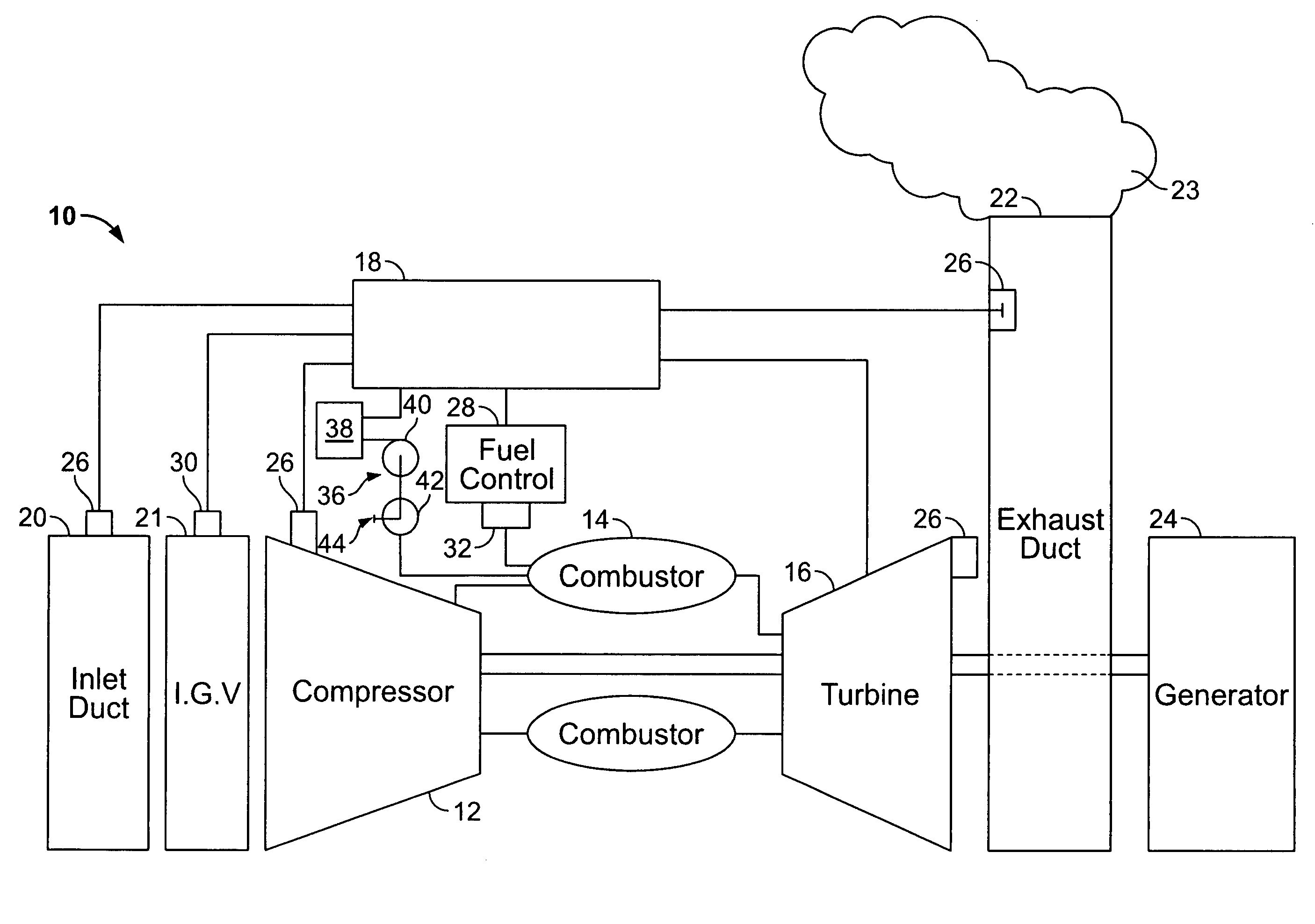
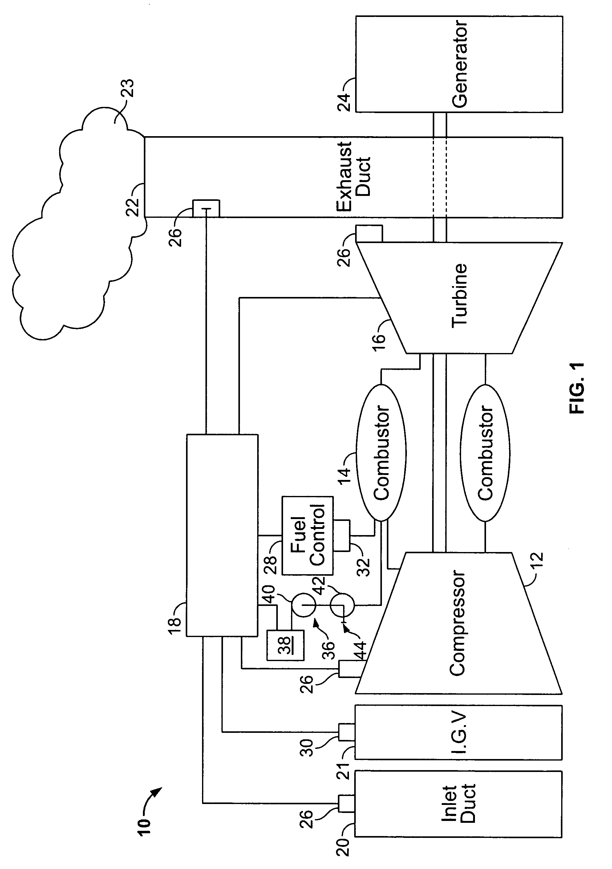
[0013]FIG. 1 is a schematic diagram of a gas turbine engine system 10 including a compressor 12, a combustor 14, a turbine 16 drivingly coupled to compressor 12, and a control system 18. An inlet duct 20 channels ambient air to the compressor. Inlet duct 20 may have ducts, filters, screens and sound absorbing devices that contribute to a pre...


PUM


Abstract

Methods and systems for a dry low NOx gas turbine engine system include a gas turbine engine including at least one dry low NOx combustor. The combustor includes a plurality of injection points wherein at least some of the injection points are configured to inject a fuel into the combustor at a plurality of different locations. The system includes a water source coupled to the combustor and operable to inject water into others of the plurality of injection points. The system also includes a control system that includes a sensor configured to measure an exhaust gas concentration of the turbine, a processor programmed to receive a signal indicative of the turbine exhaust gas concentration, and to automatically control the water injection using the received exhaust gas concentration signal. Such systems in use together can mitigate visible emissions from the exhaust stack.

Description

BACKGROUND OF THE INVENTION[0001]This invention relates generally to power generation involving the combustion of gas fossil fuels, and more particularly to methods and apparatus for reducing visible emissions in heavy-duty gas turbine power generators.[0002]The condition of a visible yellow plume emanating from the stacks of combined cycle power plants is typically caused by an NO2 concentration exiting the gas turbine engine. As gas turbines have became more sophisticated, exhaust temperatures have increased. The NO2 level exiting the stack comes generally from two sources, NO2 formed in the combustion system and conversion of NO to NO2 in the exhaust path. A higher exhaust temperature increases the amount of NO to NO2 conversion in the exhaust path. Water injection has been shown to facilitate lowering the amount of NOx produced in a combustion system. Typically, water is used in non-Dry Low NOx combustors to reduce NOx over a contractual guarantee range (usually 50%-100% load). ...

Claims


Application Information

Patent Timeline
Patent Type & Authority Patents(United States)
IPC IPC(8): F02C3/30
CPCF02C3/30F23L7/002F23R3/286F05D2270/082F05D2270/0831F23N5/003F23N2041/20Y02E20/16F23N2241/20
Inventor MOTTER, ERICZIMINSKY, WILLY STEVEFOSSUM, ARTHUR JAMESIASILLO, ROBERT JOSEPH
Owner GE INFRASTRUCTURE TECH INT LLC
Learn More