
System and method for calibrating multiple cameras without employing a pattern by inter-image homography

a multi-view video and pattern technology, applied in image analysis, instruments, computing, etc., can solve the problems of not having the ability to select viewing angles, not having the ability to exercise camera control, and watching what has been recorded and provided, so as to achieve the effect of broader network bandwidth and stronger computer processing power

Inactive Publication Date: 2009-03-31
MICROSOFT TECH LICENSING LLC
View PDF7 Cites 15 Cited by
  • Summary
  • Abstract
  • Description
  • Claims
  • Application Information

AI Technical Summary

Benefits of technology

Enables users to interactively choose camera viewpoints and angles, providing richer multimedia experiences with efficient compression and handling of large image and audio data, while being computationally robust and cost-effective.

Problems solved by technology

When reviewing conventional multimedia services (like traditional TV, video-on-demand, video streaming, digital video disc (DVD), and so on), there exist several limitations.
Furthermore, they can only watch what has been recorded and provided to them and do not have the ability to select the viewing angles.
The EyeVision system, however, only provides users with one edited video without the ability for the user to select viewing directions and exercise camera control.
It also only serves a TV audience and is not available in other multi-media formats.
However, like EyeVision, the 3D recorder does not allow the users to control the cameras.
Additionally, the processing employed by the 3D video recorder necessitates the classification of the foreground from the background which requires substantial computational assets.
With regard to the application scenarios it has been found that the multi-view video is the most challenging scenario with most incomplete, inefficient and unavailable elements.
Furthermore, no standardization efforts have dealt with interactivity.

Method used


Image

  • System and method for calibrating multiple cameras without employing a pattern by inter-image homography
  • System and method for calibrating multiple cameras without employing a pattern by inter-image homography
  • System and method for calibrating multiple cameras without employing a pattern by inter-image homography

Examples


Embodiment Construction

[0036]In the following description of the preferred embodiments of the present invention, reference is made to the accompanying drawings that form a part hereof, and in which is shown by way of illustration specific embodiments in which the invention may be practiced. It is understood that other embodiments may be utilized and structural changes may be made without departing from the scope of the present invention.

1.0 Exemplary Operating Environment

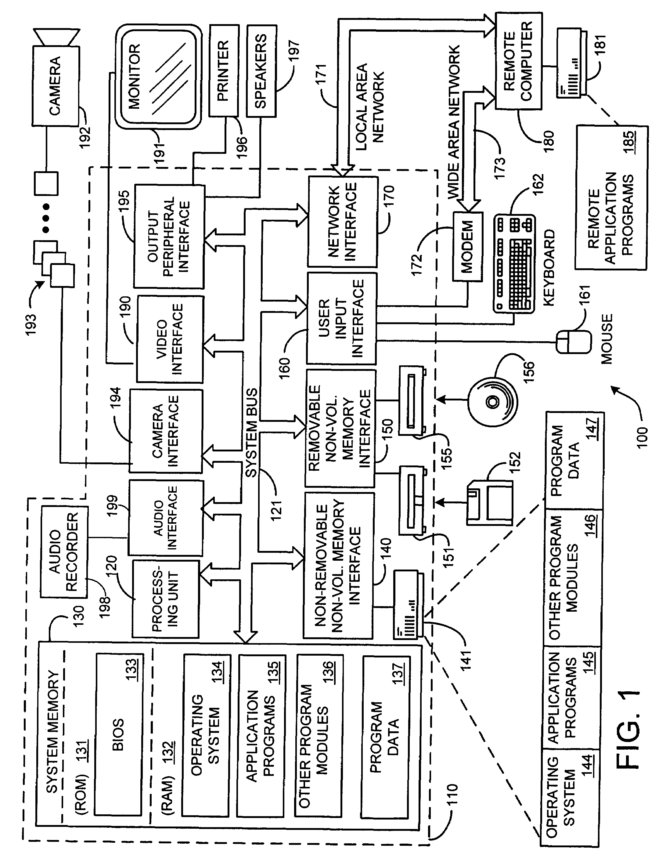
[0037]FIG. 1 illustrates an example of a suitable computing system environment 100 on which the invention may be implemented. The computing system environment 100 is only one example of a suitable computing environment and is not intended to suggest any limitation as to the scope of use or functionality of the invention. Neither should the computing environment 100 be interpreted as having any dependency or requirement relating to any one or combination of components illustrated in the exemplary operating environment 100.

[0038]The inventi...


PUM


Abstract

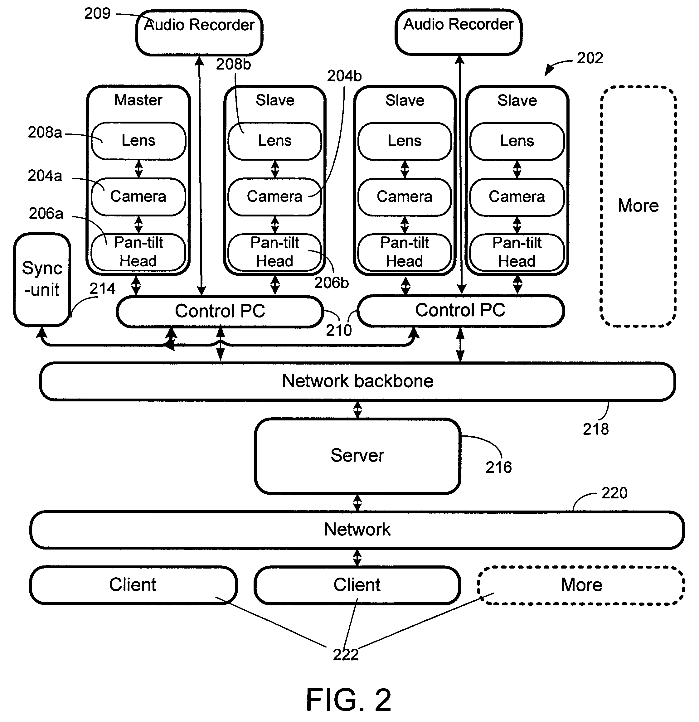
Interactive multi-view video presents new types of video capture systems, video formats, video compression algorithms, and services. Many video cameras are allocated to capture an event from various related locations and directions. The captured videos are compressed in control PCs and are sent to a server in real-time. Users can subscribe to a new type of service that allows users to connect to the servers and receive multi-view videos interactively. In one embodiment of the invention, an automatic pattern-free calibration tool is employed to calibrate the multiple cameras. In contrast with a pattern-based method which uses the correspondences between image points and pattern points, the pattern-free calibration method is based on the correspondences between image points from different views.

Description

[0001]This is a divisional application of application Ser. No. 10 / 901,477, filed Jul. 27, 2004.BACKGROUND[0002]1. Technical Field[0003]This invention is directed toward a system and method for interactive multi-view video which includes a new type of system and method for calibrating multiple cameras without employing a calibration pattern.[0004]2. Background Art[0005]The current popularly used video form is so-called single-view video. It consists of one video clip that is captured from one video camera or multiple video clips that are concatenated using sequential time periods. For any time instance, there is only one view of an event. This kind of video form is widely used in video streaming, broadcasting and communication in televisions (TVs), personal computers (PCs) and other devices.[0006]When reviewing conventional multimedia services (like traditional TV, video-on-demand, video streaming, digital video disc (DVD), and so on), there exist several limitations. For example, in...

Claims


Application Information

Patent Timeline
Patent Type & Authority Patents(United States)
IPC IPC(8): G06K9/00G06V10/147
CPCG06K9/209G06T7/0018G06T7/80G06V10/147
Inventor LOU, JIANGUANGLI, JIANGCAI, HUA
Owner MICROSOFT TECH LICENSING LLC
Learn More