Eureka AIR delivers breakthrough ideas for toughest innovation challenges, trusted by R&D personnel around the world.

Magnetic resonance imaging apparatus and RF coil

a magnetic resonance imaging and rf coil technology, applied in the direction of instruments, magnetic measurements, measurement devices, etc., can solve the problems of uneven transmission, inability to use such a technique as the sense method, and differences in sensitivity distribution or efficiency among the coils

Inactive Publication Date: 2009-03-31
GE MEDICAL SYST GLOBAL TECH CO LLC
View PDF12 Cites 7 Cited by
  • Summary
  • Abstract
  • Description
  • Claims
  • Application Information

AI Technical Summary

Benefits of technology

[0004]Therefore, an object of the present invention is to provide a magnetic resonance imaging apparatus capable of receiving magnetic resonance signals with a plurality of coil while uniformly exciting such signals, an RF coil and a method of controlling the magnetic resonance imaging apparatus.

Problems solved by technology

Where transmission and reception are performed with a plurality of coils, unevenness in transmission results from differences in sensitivity distribution or efficiency among the coils.
On the other hand, where transmission and reception are performed with a single coil, unevenness in transmission can be restrained, but no such technique as the SENSE method can be used.

Method used


Image

  • Magnetic resonance imaging apparatus and RF coil
  • Magnetic resonance imaging apparatus and RF coil
  • Magnetic resonance imaging apparatus and RF coil

Examples


Embodiment Construction

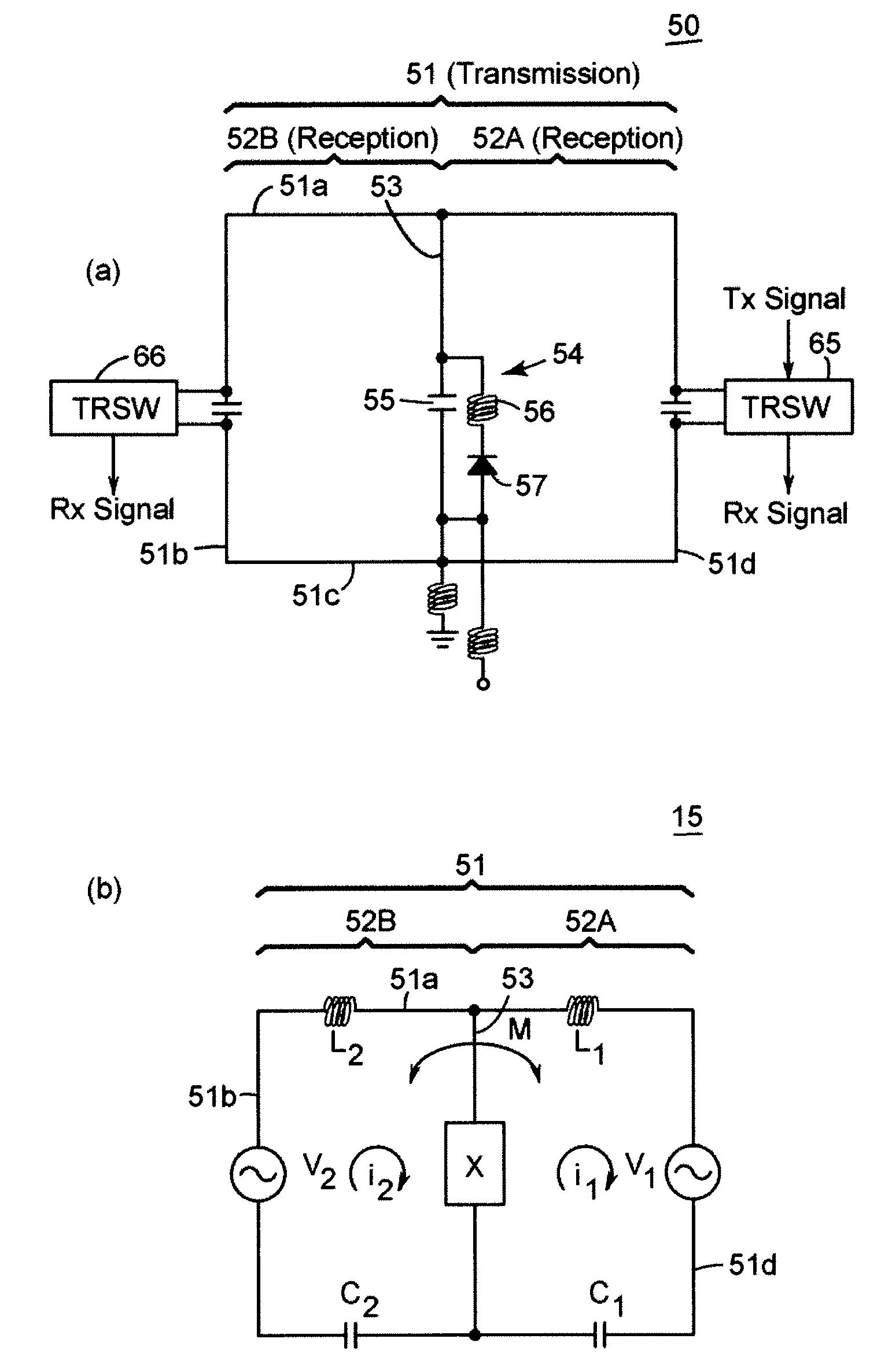
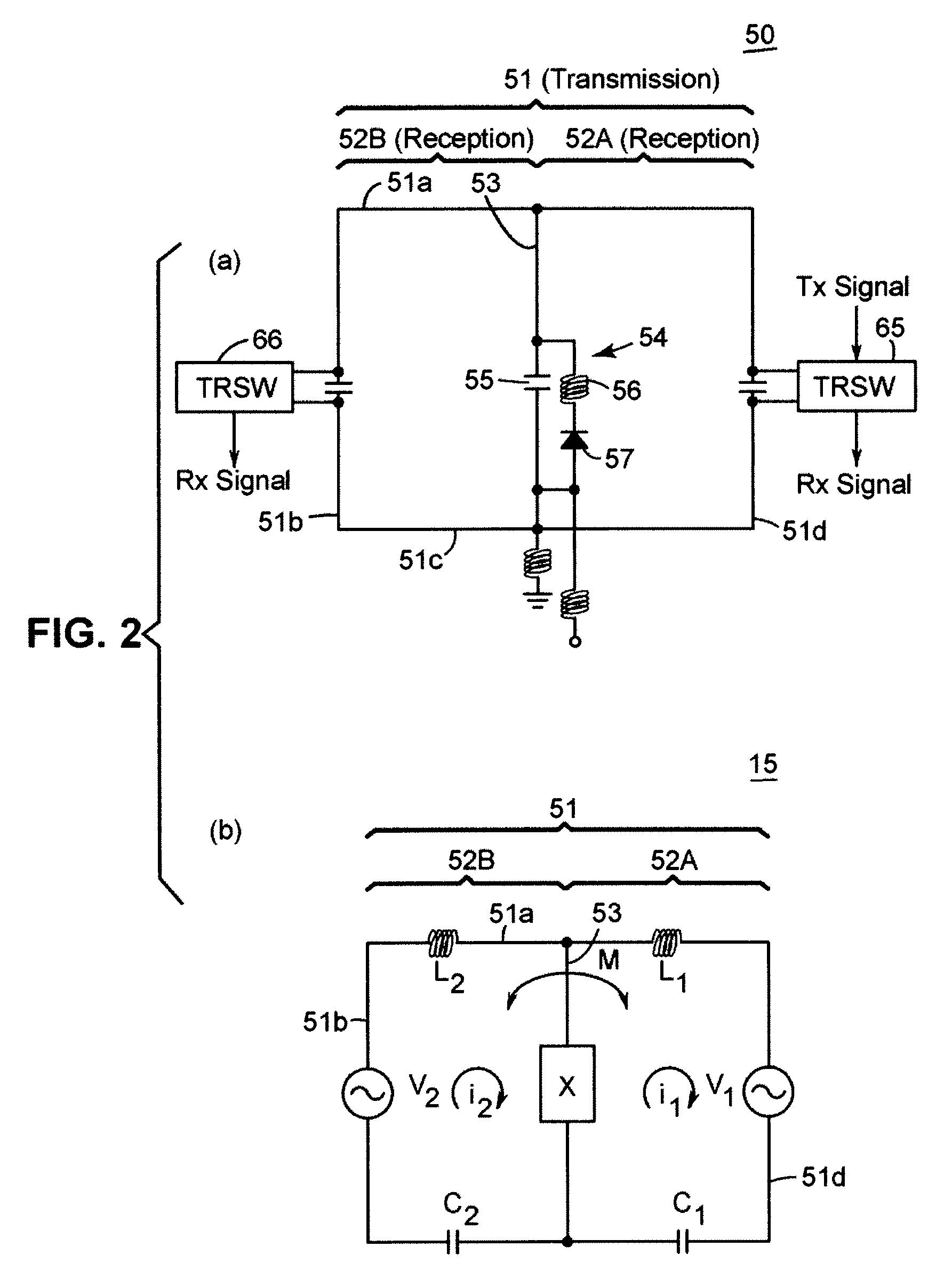
[0022]Exemplary Mode for Implementation 1 FIG. 1 is a block diagram showing a schematic configuration of a magnetic resonance imaging apparatus (MRI) 1 in this mode for implementation. The magnetic resonance imaging apparatus has a magnetostatic magnet unit 12, a gradient coil 13, an RF coil 15, an the RF drive unit 22, a gradient drive unit 23, a data collecting unit 24, a switch-over drive unit 25, a control unit 26, a cradle 27, a data processing unit 31, an operation unit 32 and a display unit 33.

[0023]The magnetostatic magnet unit 12 is intended for forming a magnetostatic field in a imaging space B in which a subject is accommodated. The magnetostatic magnet unit 12 is configured of a pair of permanent magnets. And the magnetostatic magnet unit 12 is so configured that the direction of the magnetostatic field is along the direction of the body axis of the subject SU or a direction normal to the body axis. Incidentally, the magnetostatic magnet unit 12 may as well be configured...


PUM


Abstract

A magnetic resonance imaging apparatus capable of receiving magnetic resonance signals with a plurality of coils while uniformly exciting such signals is to be provided. An RF coil of the magnetic resonance imaging apparatus is provided with an original loop unit, and a conductor which is so connected to the original loop unit as to split the original loop unit into split loop units. A control unit applies a high frequency magnetic field with the original loop unit and receives magnetic resonance signals with the split loop units.

Description

BACKGROUND OF THE INVENTION[0001]The present invention relates to a magnetic resonance imaging apparatus, an RF coil and a method of controlling the magnetic resonance imaging apparatus.[0002]For magnetic resonance imaging apparatuses, there is known a method by which magnetic resonance signals are excited with a plurality of coils such as phased array coils, and the excited magnetic resonance signals are received to create images by an image synthesizing method such as the sum-of-squares method or the SENSE method (see, for instance, JP-A No. 250776 / 2003). There is also known a method by one loop of an RF coil is split into a plurality of sub-loops, and the size of the RF coil is made changeable by receiving magnetic resonance signals with the loop before splitting or one of the sub-loops resulting from the splitting (see, for instance, JP-A No. 290168 / 2003).[0003]Where transmission and reception are performed with a plurality of coils, unevenness in transmission results from diffe...

Claims


Application Information

Patent Timeline
Patent Type & Authority Patents(United States)
IPC IPC(8): G01V3/00
CPCG01R33/34046G01R33/3415G01R33/5611
Inventor FUJIMOTO, MASAHIROYOSHIDA, MASARU
Owner GE MEDICAL SYST GLOBAL TECH CO LLC
Why Eureka
Eureka Blog
Learn More