
Viscosity determination from logarithmic mean ratio of relaxation times

a technology of relaxation times and viscosity, applied in the field of borehole fluid assessment, can solve the problems of unreachable use of nmr for viscosity determination, ,

Active Publication Date: 2009-03-31
BAKER HUGHES INC
View PDF9 Cites 12 Cited by
  • Summary
  • Abstract
  • Description
  • Claims
  • Application Information

AI Technical Summary

Problems solved by technology

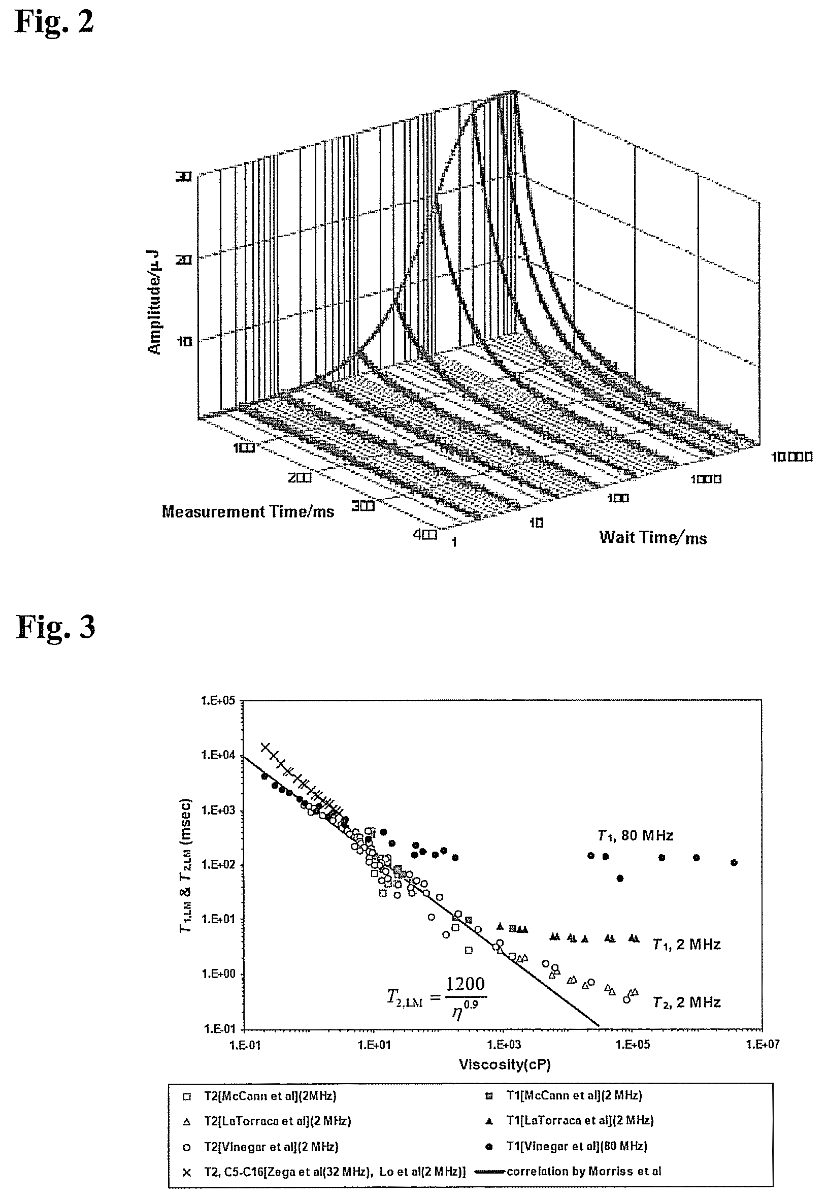
Unfortunately, in the prior art, reliable use of NMR for determining viscosity, η, has not been realized.

Method used


Image

  • Viscosity determination from logarithmic mean ratio of relaxation times
  • Viscosity determination from logarithmic mean ratio of relaxation times
  • Viscosity determination from logarithmic mean ratio of relaxation times

Examples


Embodiment Construction

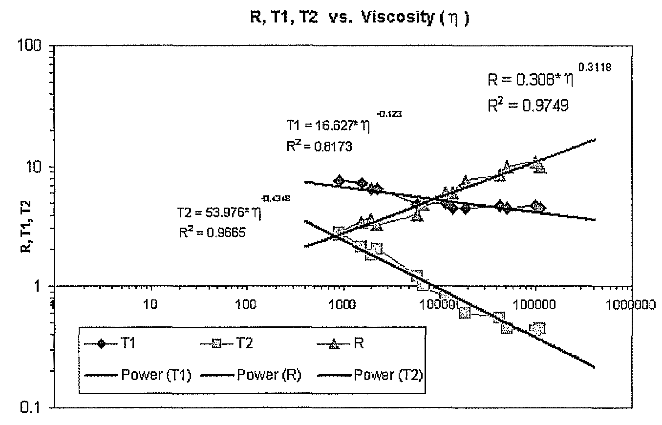
[0016]The teachings herein take advantage of various unique nuclear magnetic resonance (NMR) properties of materials to provide for determination of fluid viscosity downhole.

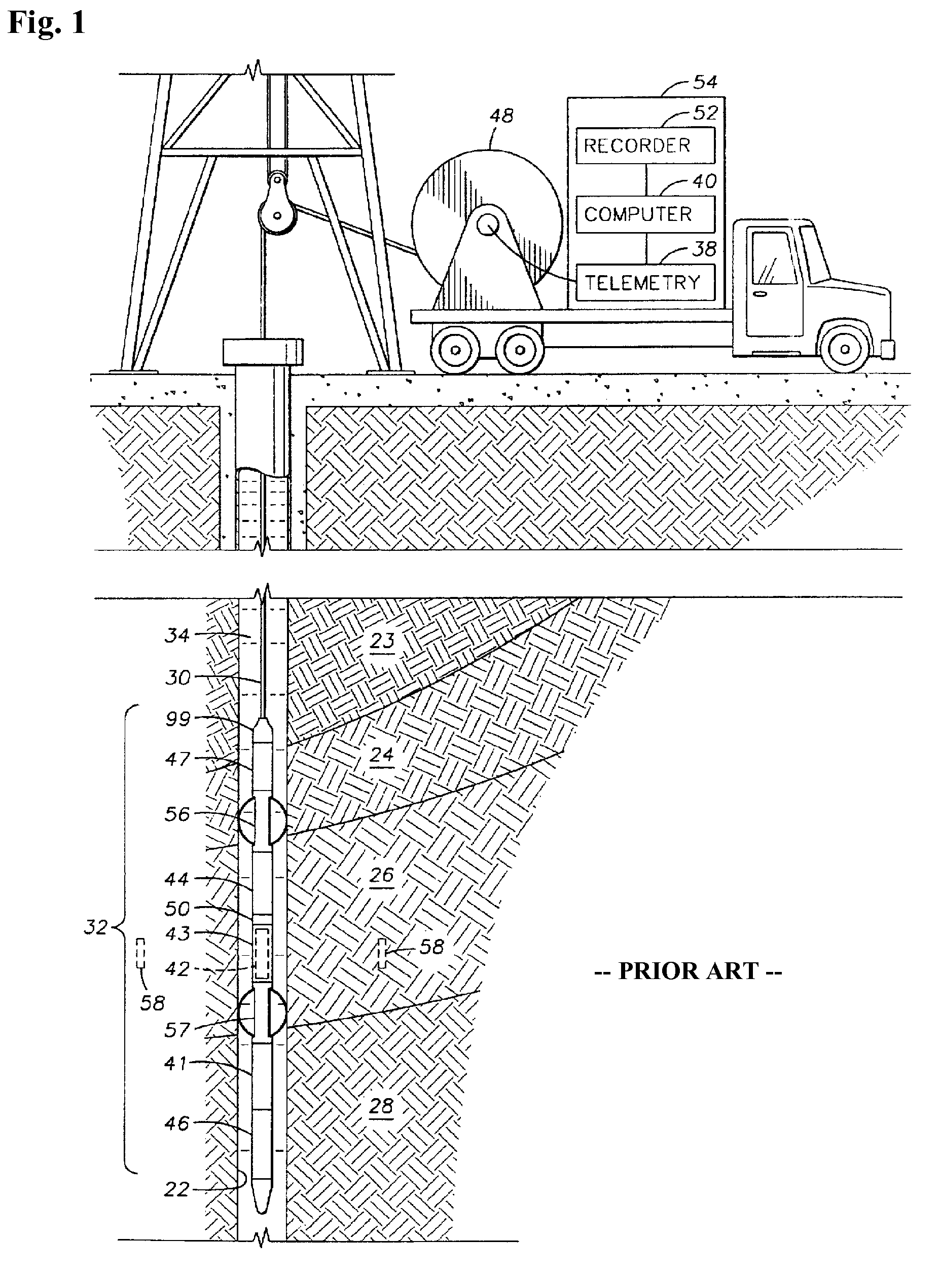
[0017]First, turn to FIG. 1 to consider aspects of downhole NMR characterizations, using a non-limiting embodiment of a wireline logging device. One skilled in the art will recognize that the techniques disclosed herein can be applied with other embodiments, such as logging-while-drilling (LWD) or measurements-while-drilling (MWD) operations.

[0018]FIG. 1 shows a well logging apparatus disposed in a wellbore 22 penetrating earth formations 23, 24, 26, 28 for making measurements of properties of the earth formations 23, 24, 26, 28 downhole. The wellbore 22 in FIG. 1 is typically filled with a fluid 34 known in the art as “drilling mud.” A “sensitive volume,” shown generally at 58 and having a generally cylindrical shape, is disposed in one of the earth formations, shown at 26. The sensitive volume 58 is a predeter...


PUM


Abstract

A method for determining viscosity, η, of a fluid downhole, calls for performing a nuclear magnetic resonance (NMR) survey of the fluid; determining a longitudinal relaxation time, T1, and an apparent transverse relaxation time, T2app, for the fluid; forming a ratio R of T1 / T2app for the fluid; and determining the viscosity, η, according to the ratio, R. A computer program product for implementing the method is provided.

Description

BACKGROUND OF THE INVENTION[0001]1. Field of the Invention[0002]This invention relates to assessments of borehole fluids, and in particular to determination of viscosity by use of nuclear magnetic resonance.[0003]2. Description of the Related Art[0004]Downhole characterization techniques are of considerable value for geophysical exploration. For example, characterization of parameters associated with downhole fluids provides for insight into quality of the fluid. More specifically, knowledge of viscosity, η, can provide insight into the quality of hydrocarbons in a formation. A number of technologies are applied downhole for various tasks. These technologies include nuclear magnetic resonance (NMR) imaging. Unfortunately, in the prior art, reliable use of NMR for determining viscosity, η, has not been realized.[0005]Therefore, what is needed is a technique for estimating viscosity, η, of downhole fluids by use of NMR technologies.BRIEF SUMMARY OF THE INVENTION[0006]A method for dete...

Claims


Application Information

Patent Timeline
Patent Type & Authority Patents(United States)
IPC IPC(8): G01V3/00
CPCG01N24/081G01R33/5615G01V3/32G01R33/448G01R33/44
Inventor ROMERO, PEDRO ANTONIOSAAVEDRA, BENITO EDUARDOKWAK, HYUNG TAEHURSAN, GABOR
Owner BAKER HUGHES INC
Learn More