Voltage regulator
a voltage regulator and voltage terminal technology, applied in the field of voltage regulators, can solve the problems of reducing the current for charging the external capacitor connected with the output voltage terminal, and prolonging the rise time of the output voltage of the voltage regulator, so as to reduce the rise time of the output voltage and limit the current of the output circui
- Summary
- Abstract
- Description
- Claims
- Application Information
AI Technical Summary
Benefits of technology
Problems solved by technology
Method used
Image
Examples
embodiment 1
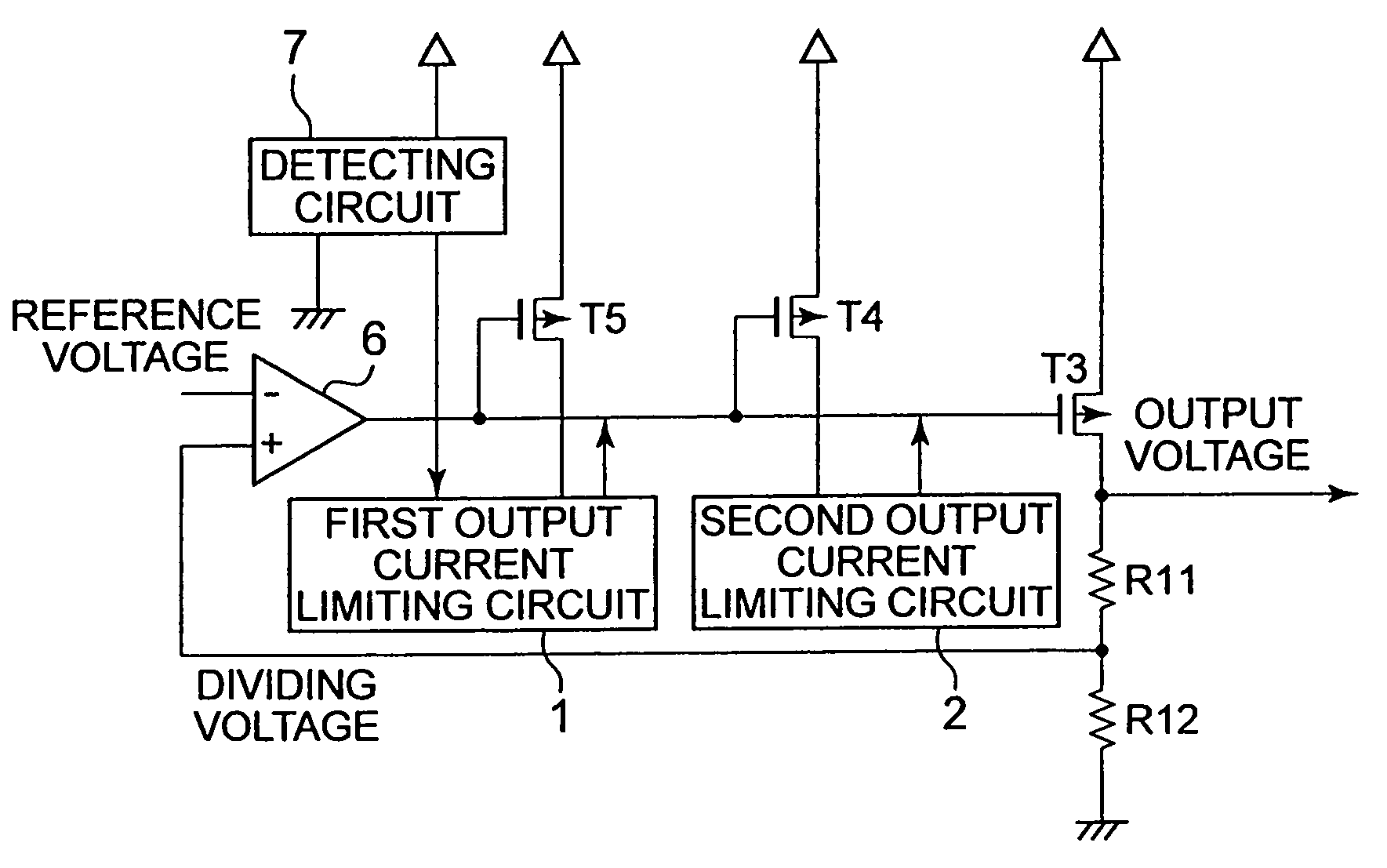
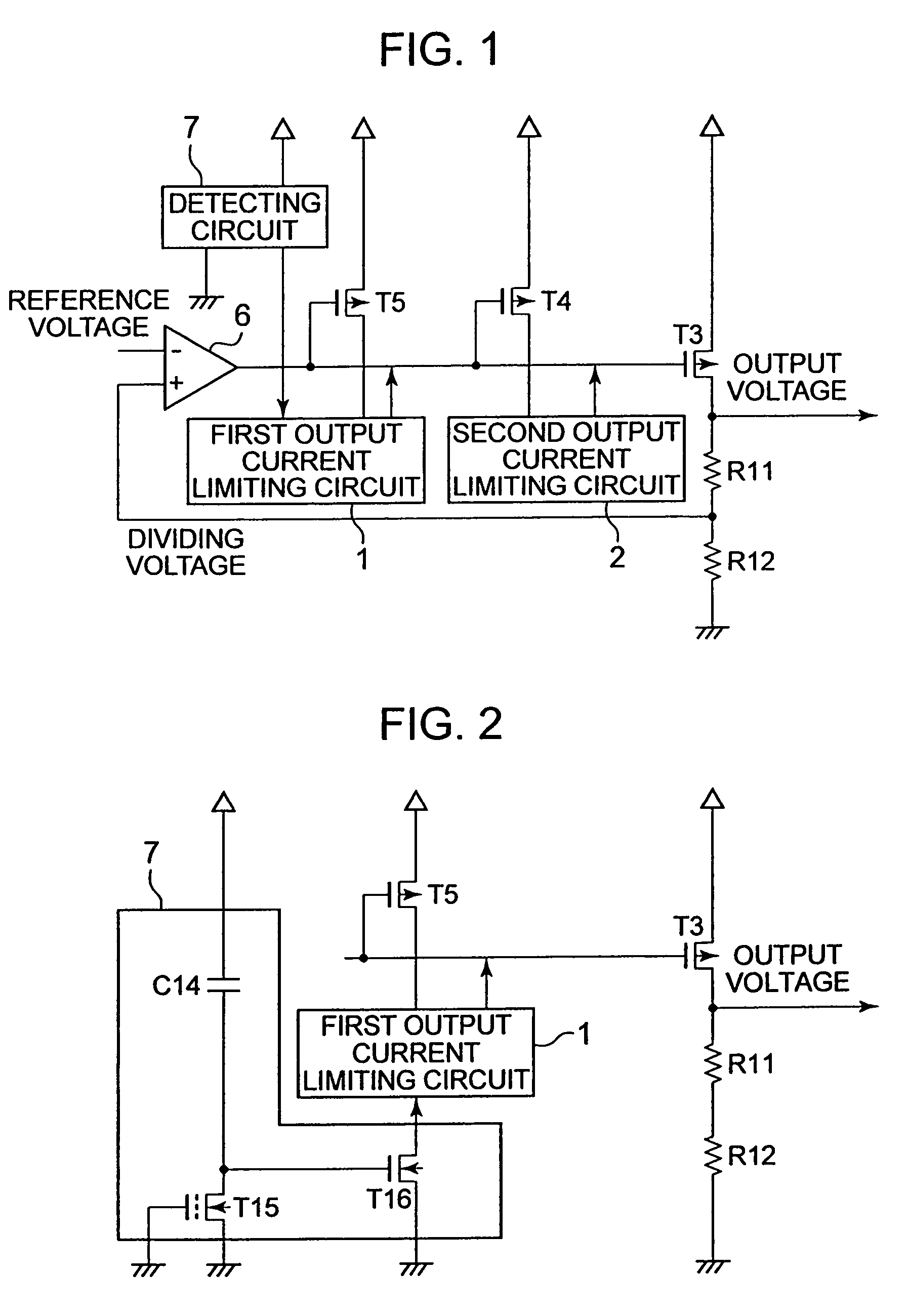
[0020]FIG. 1 is a block diagram showing a voltage regulator according to Embodiment 1.
[0021]The voltage regulator according to Embodiment 1 includes an amplifying circuit 6 for comparing a dividing voltage obtained by dividing an output voltage by resistors R11 and R12 with a reference voltage, a PMOS transistor T3 (output circuit) whose gate is connected with an output terminal of the amplifying circuit 6, a PMOS transistor T5 (first output current detecting circuit) whose gate is connected with the output terminal of the amplifying circuit 6, a first output current limiting circuit 1 for controlling a gate voltage of the PMOS transistor T3 based on a drain current of the PMOS transistor T5, a PMOS transistor T4 (second output current detecting circuit) whose gate is connected with the output terminal of the amplifying circuit 6, a second output current limiting circuit 2 for controlling a gate voltage of the PMOS transistor T3 based on a drain current of the PMOS transistor T4, an...
embodiment 2
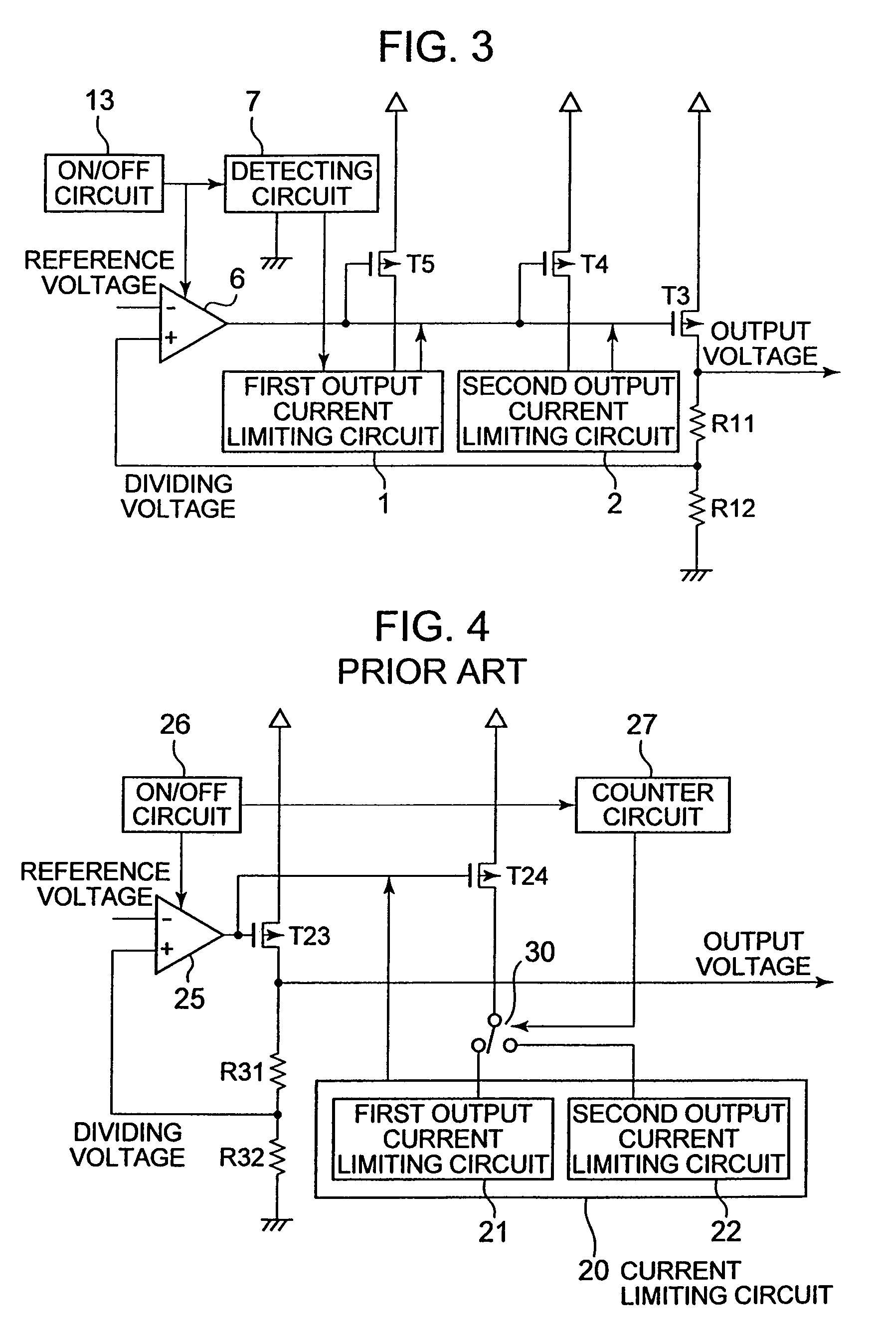
[0034]FIG. 3 is a block diagram showing a voltage regulator according to Embodiment 2. The voltage regulator according to Embodiment 2 has a structure in which an on / off circuit 13 is further provided in the voltage regulator according to Embodiment 1.
[0035]The on / off circuit 13 performs the on / off control of the voltage regulator. The on / off circuit 13 has an output terminal connected with the amplifying circuit 6 and the detecting circuit 7. The on / off circuit 13 outputs a control signal to each of the amplifying circuit 6 and the detecting circuit 7 in response to a signal from an outside to perform the on / off control of the voltage regulator.
[0036]The voltage regulator according to Embodiment 2 operates as follows.
[0037]When the voltage regulator is turned on, the on / off circuit 13 outputs the control signal to each of the amplifying circuit 6 and the detecting circuit 7 to turn on the voltage regulator. Then, the detecting circuit 7 detects the rise speed of the input voltage. ...
PUM
 Abstract
Description
Claims
Application Information
 - R&D
- Intellectual Property
- Life Sciences
- Materials
- Tech Scout
- Unparalleled Data Quality
- Higher Quality Content
- 60% Fewer Hallucinations
Browse by: Latest US Patents, China's latest patents, Technical Efficacy Thesaurus, Application Domain, Technology Topic, Popular Technical Reports.
© 2025 PatSnap. All rights reserved.Legal|Privacy policy|Modern Slavery Act Transparency Statement|Sitemap|About US| Contact US: help@patsnap.com


