
Method of making wide field spherical lenses and protective eyewear

Inactive Publication Date: 2009-03-24
CARL ZEISS VISION INC
View PDF132 Cites 10 Cited by
  • Summary
  • Abstract
  • Description
  • Claims
  • Application Information

AI Technical Summary

Benefits of technology

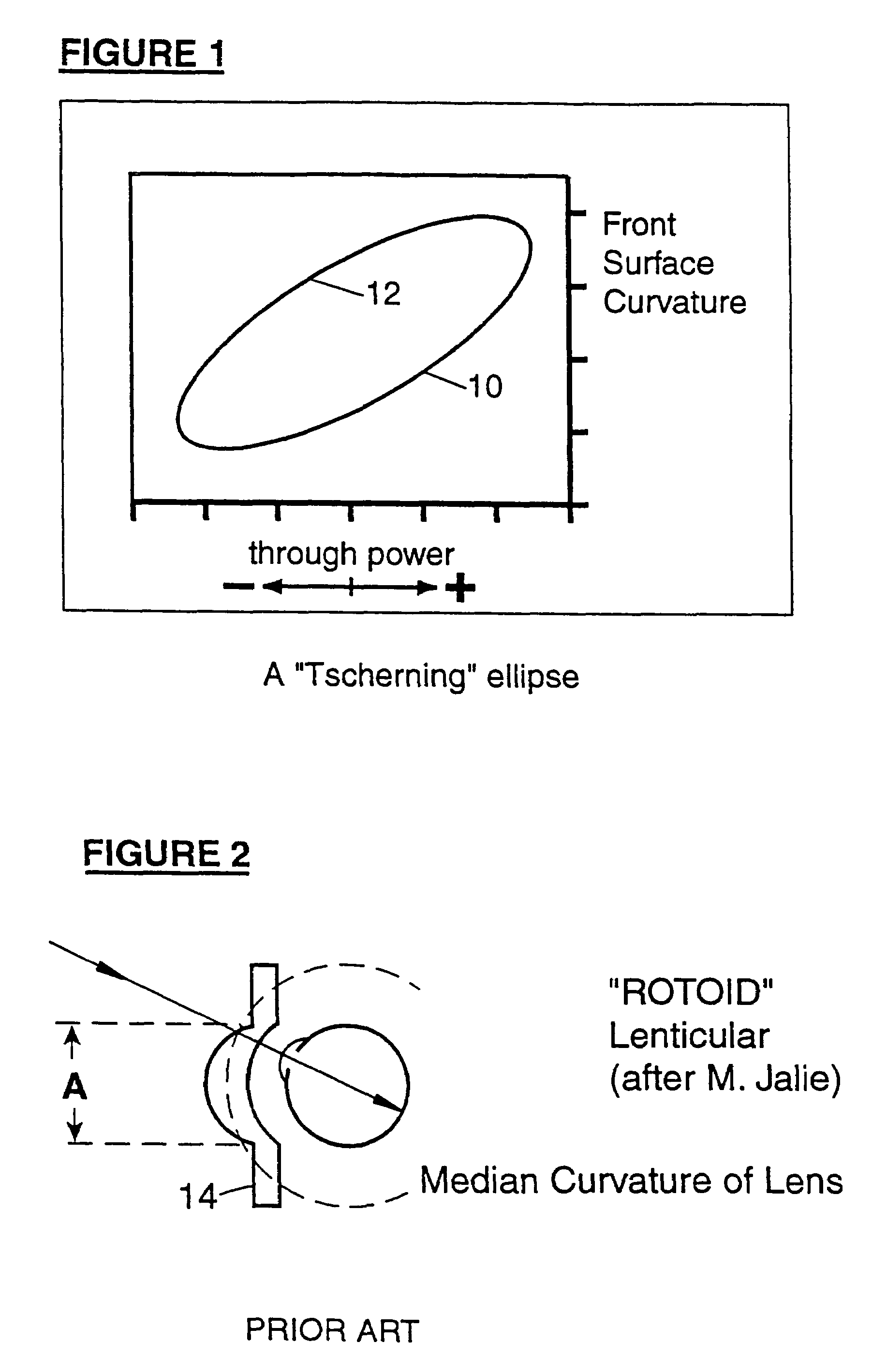
[0012]Applicants have studied the properties of steeply curved lenses and considered series of lenses having commonly prescribed plus or minus through powers. Applicants observed that such lenses could, in principle, provide a wide field of view and eye protection. However, certain problems would interfere with practical implementation of such wide-field lens. Generally there are problems of fabrication and distortion, and problems of producing a range of common plus or minus power prescriptions with or without available common astigmatism correction or “cy1” prescriptions.
[0013]A more subtle problem is presented by the wide range of front surface powers which would be required to provide a range of common prescription powers. For the lens assumptions of FIG. 1, for example, the Wollaston section would be understood to teach a variation in front surface power of from about 15 D to about 20 D for a product line through-power range of from +5 D to −8 D. This corresponds to a variatio

Problems solved by technology

Such lenses provide a limited field of view due to peripheral distortion and / or physical size limitations.
Their relatively flat shapes limit the amount of eye protection afforded by the lenses, particularly near the temples.
However, wrap-around eyewear is typically non-prescription.
This causes the line of sight of the wearer to deviate from the optical axis, and optical performance is often significantly degraded.
Peripheral vision is typically poor.
Because of difficulties in fabrication, such early lenses were probably of small aperture and, consequently, perhaps, regarded as unacceptable for cosmetic reasons and because of their limited field of view.
However, certain problems would interfere with practical implementation of such wide-field lens.
Generally there are problems of fabrication and distortion, and problems of producing a range of common plus or minus power prescriptions with or without available common astigmatism correction or “cy1” prescriptions.
A more subtle problem is presented by the wide range of front surface powers which would be required to provide a range of common prescription powers.
While such unique styles have value, they are incompatible with providing mass-marketed eyewear with a consistent appearance.

Method used


Image

  • Method of making wide field spherical lenses and protective eyewear
  • Method of making wide field spherical lenses and protective eyewear
  • Method of making wide field spherical lenses and protective eyewear

Examples


example 1

[0149]Table 1 shows a comparison of the calculated performance of a polycarbonate lens made in accordance with the present invention and a conventional low base curve lens.

[0150]

ConcentricformConventionalIndex of refraction1.5861.586Power−3.00−3.00 dioptersThickness2.02.0 in mmFront Surface Curvature (1.53016.004.00 diopterstooling indexFront Surface Radius33.1132.5 mmOptical power of front surface17.74.4 diopters (higher due to1.586 index)Paraxial Magnification0.970.96Apparent field of view130105 in degrees, for the edgeoutline of FIG. 10(a)Optical Values at 30 degree eyerotation:Distortion−1.10%−3.10%Astigmatism0.020.17 dioptersMean Power Error0.070.025 dioptersRMS Power Error0.070.09Chromatic Abberation0.110.16 prism diopters

example 2

[0151]FIG. 19 illustrates a calculated comparison between a series of steeply curved spherical lens elements of −6 D, −3 D and +3 D power [FIGS. 19(a), (c) and (e), respectively] with corresponding low base curve Sola Perma-Poly™ stock lenses [FIGS. 19(b), (d) and (f), respectively].

[0152]The steeply curved spherical lens elements have essentially identical, spherical front surfaces of 16 D as shown in the lens cross sections 400. Generally, the steeply curved spherical lens elements provide superior peripheral distortion. The lenses of FIGS. 19(a) and 19(c) also exhibit reduced RMS power error in the minus prescriptions.

example 3

[0153]FIG. 20 illustrates a calculated comparison between two steeply curved spherical lens elements with a 16 D front surface −3 D through power and a back surface cyl correction of −2.

[0154]The lens of FIG. 20(a) has a conventional donut torus back; the lens of FIG. 20(b) has an all circular meridia back of the type described above. The latter exhibits superior RMS power error and somewhat improved distortion.


PUM

PropertyMeasurementUnit
Lengthaaaaaaaaaa
Lengthaaaaaaaaaa
Lengthaaaaaaaaaa

Abstract

The present invention relates to novel ophthalmic lens elements and eyewear having wide field of view, low distortion, improved astigmatism correction where required and enhanced eye protection properties. Series of lens elements have steeply curved spherical reference surfaces. The edged lenses of the series have approximately consistent aperture size, shape and hollow depth across a range of common prescriptions. Novel sunglasses, laser protective eyewear, and lens edgings, coatings and frames are included in the invention.

Description

RELATED APPLICATIONS[0001]This application is a divisional of U.S. patent application Ser. No. 09 / 698,270 filed Oct. 30, 2000 now U.S. Pat. No. 6,682,193, which is a continuation-in-part of application Ser. No. 09 / 658,496 filed Sep. 8, 2000 now U.S. Pat. No. 6,440,335, which issued on Aug. 27, 2002.[0002]The '270 application and the '335 patent are also continuations-in-part of application Ser. No. 09 / 223,006, filed Dec. 30, 1998, now U.S. Pat. No. 6,142,624, which issued on Nov. 7, 2000, which application is hereby incorporated by reference in its entirety.[0003]The '270 application is also a continuation-in-part of International Application No. PCT / AU99 / 01029 to Yip et al. filed internationally on Nov. 19, 1999 with the U.S. as a designated state, published on Jun. 8, 2000 as WO 00 / 33111, which application is hereby incorporated by reference in its entirety.FIELD OF THE INVENTION[0004]The present invention relates to improved ophthalmic lens elements and eyewear, including prescri...

Claims


Application Information

Patent Timeline
IPC IPC(8): B29D11/00G02C7/02B29C45/56
CPCB29C45/561B29D11/00009G02C7/02B29L2011/0016
Inventor MORRIS, MICHAEL ALANPERROTT, COLIN MAURICEEDWARDS, SIMON J.SPRATT, RAY STEVEN
Owner CARL ZEISS VISION INC
Learn More