Electrical rotation machine and a wind turbine system
a technology of electric rotation machine and wind turbine, which is applied in the direction of wind energy generation, dynamo-electric machines, electrical apparatus, etc., can solve the problems of distorting induced voltage waveforms and problems, and achieve the effect of reducing the distortion factor of induced voltage waveforms
- Summary
- Abstract
- Description
- Claims
- Application Information
AI Technical Summary
Benefits of technology
Problems solved by technology
Method used
Image
Examples
embodiment 1
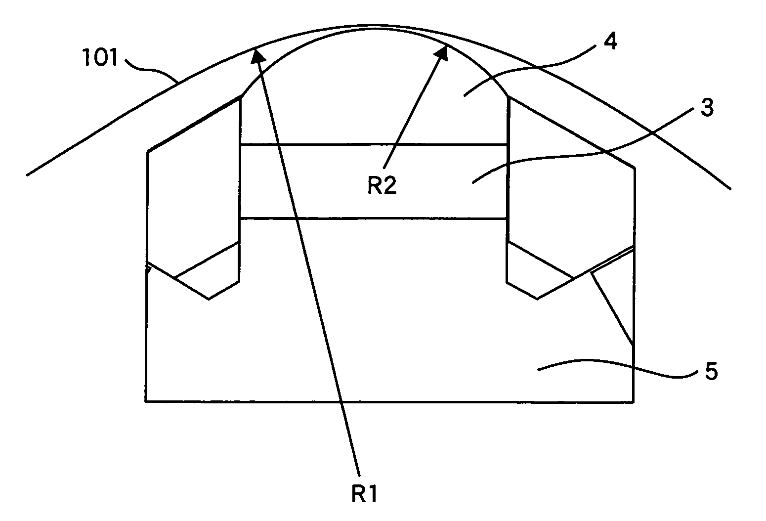
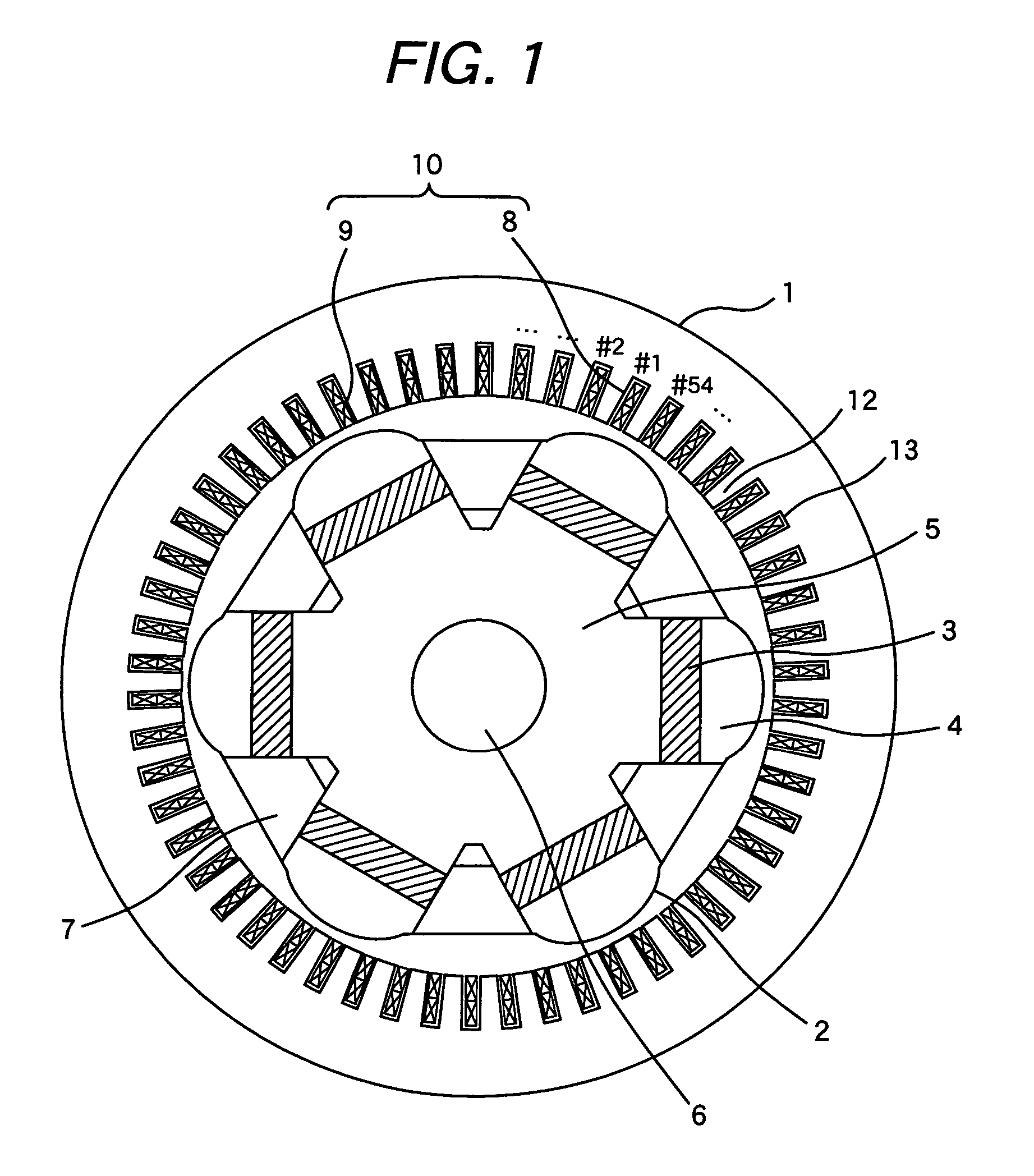
[0025]FIG. 1 is a sectional view of the end of a 6-pole 54-slot permanent magnet type electric rotation machine which is a first embodiment of this invention. This machine is better suited for a wind turbine system of a few megawatts (MW) which allows a speed of 1000 to 2000 rpm. Stator 1 is of a distributed winding type which distributionally winds coil 10 around stator teeth 12. Coil 10 has windings of three phases (U, V, and W) which are disposed so that 6 poles are electrically formed by 54 slots. Each stator slot 13 between stator teeth 12 contains upper coil 8 and lower coil 9 as shown in the drawing. In Embodiment 1, coil 10 is wound in a so-called distributed winding manner to form 3-phase windings along the periphery. Rotor 2 is provided in the center of rotor 1 so as to rotate. On rotor 2, permanent magnet 3 is provided between rotor core 5 and pole piece 4. Further, rotor core 5 is coupled with shaft 6. Pole retainer 7 is provided between two adjoining poles to prevent pe...
embodiment 2
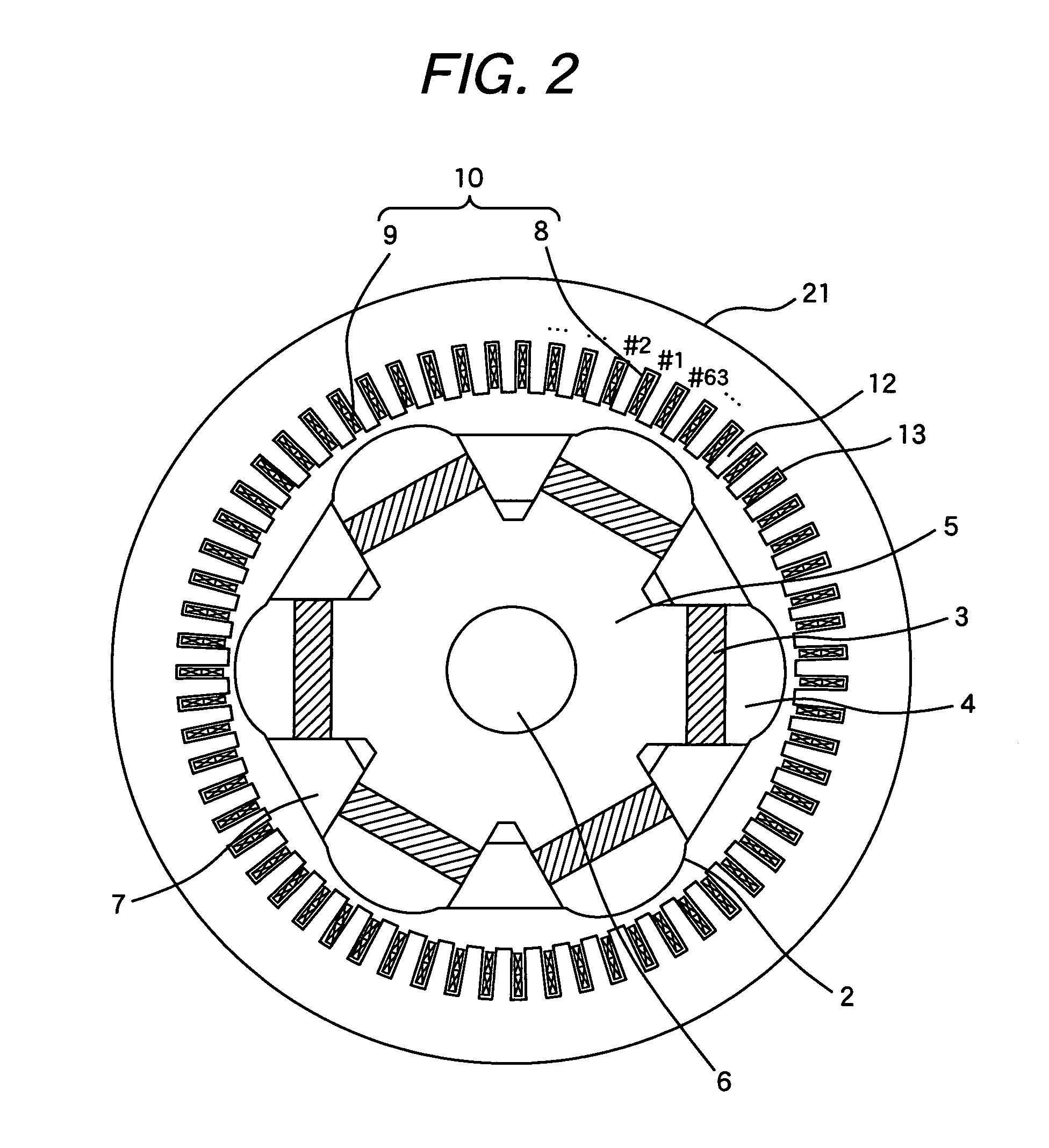
[0026]FIG. 2 is a sectional view of the end of a 6-pole 63-slot permanent magnet type electric rotation machine which is a second embodiment of this invention. In Embodiment 2 as well as Embodiment 1, coils 10 are wound distributionally around stator 21 in a so-called distributed winding manner to form 3-phase windings along the periphery. Rotor 2 is provided in the center of rotor 1 so as to rotate. On rotor 2, permanent magnet 3 is provided between rotor core 5 and pole piece 4. Further, rotor core 5 is coupled with shaft 6. Pole retainer 7 is provided between two adjoining poles to prevent permanent magnet 3 from moving circumferentially. It is preferable that the pole retainer 7 is made of a non-magnetic material such as aluminum or copper.
embodiment 3
[0027]FIG. 3 is a sectional view of the end of a 6-pole 45-slot permanent magnet type electric rotation machine which is a third embodiment of this invention. In Embodiment 3 as well as Embodiment 1, coils 10 are wound distributionally around stator 1 in a so-called distributed winding manner to form 3-phase windings along the periphery. Rotor 2 is provided in the center of stator 1 so as to rotate. On rotor 2, permanent magnet 3 is provided between rotor core 5 and pole piece 4. Further, rotor core 5 is coupled with shaft 6. Pole retainer 7 is provided between two adjoining poles to prevent permanent magnet 3 from moving circumferentially. It is preferable that the pole retainer 7 is made of a non-magnetic material such as aluminum or copper.
[0028]FIG. 4 shows the result of analysis of harmonic components in the induced voltage waveform of Embodiment 1. As shown in FIG. 4, the induced voltage waveform contains 17th and 19th harmonic components more with respect to the first harmoni...
PUM
 Abstract
Description
Claims
Application Information
 - R&D
- Intellectual Property
- Life Sciences
- Materials
- Tech Scout
- Unparalleled Data Quality
- Higher Quality Content
- 60% Fewer Hallucinations
Browse by: Latest US Patents, China's latest patents, Technical Efficacy Thesaurus, Application Domain, Technology Topic, Popular Technical Reports.
© 2025 PatSnap. All rights reserved.Legal|Privacy policy|Modern Slavery Act Transparency Statement|Sitemap|About US| Contact US: help@patsnap.com


