Retinal image display device
a display device and retinal technology, applied in the field of retinal image display devices, can solve the problems of difficult to achieve a variation of focusing condition providing a natural feel
- Summary
- Abstract
- Description
- Claims
- Application Information
AI Technical Summary
Benefits of technology
Problems solved by technology
Method used
Image

Examples
first embodiment
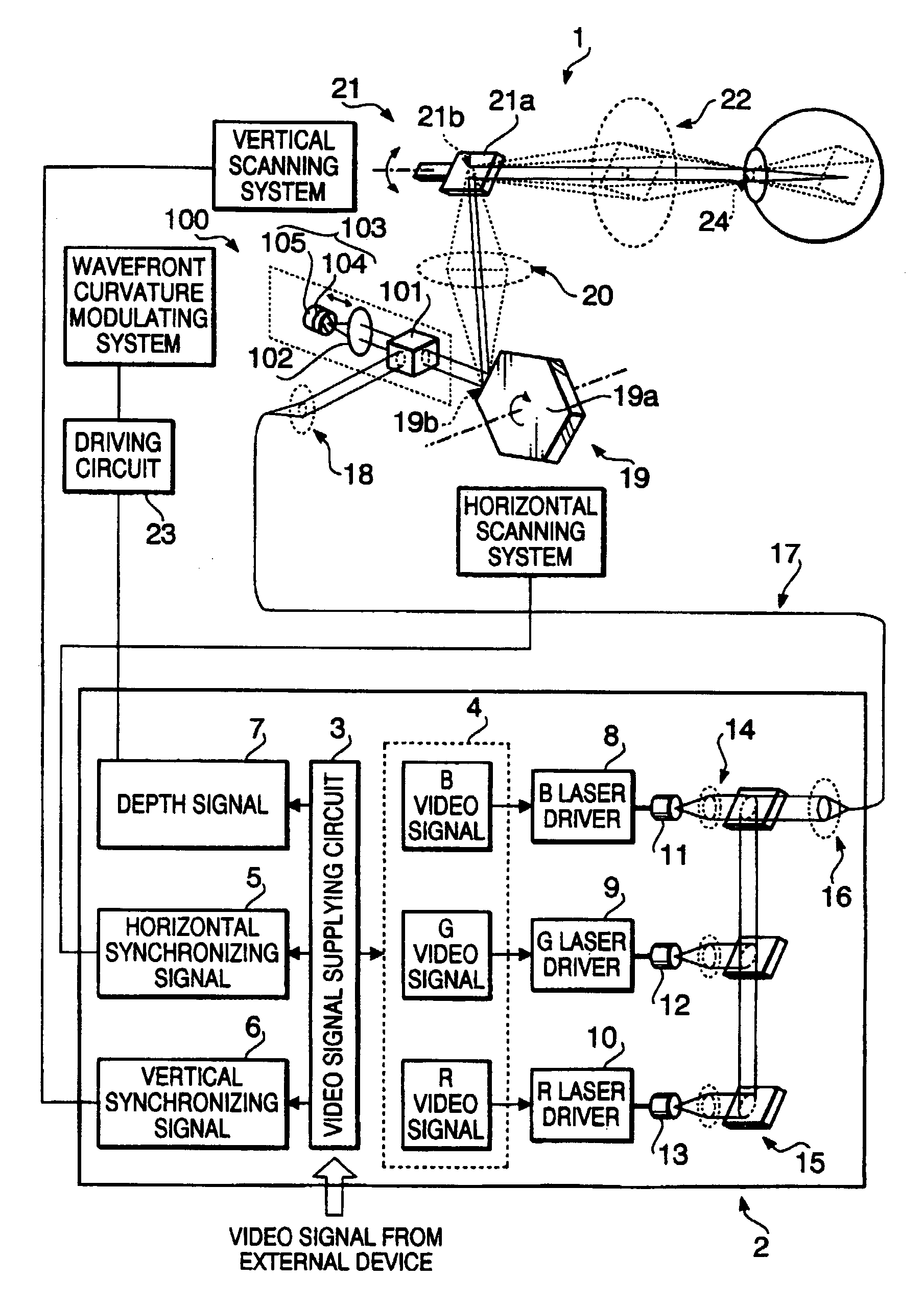
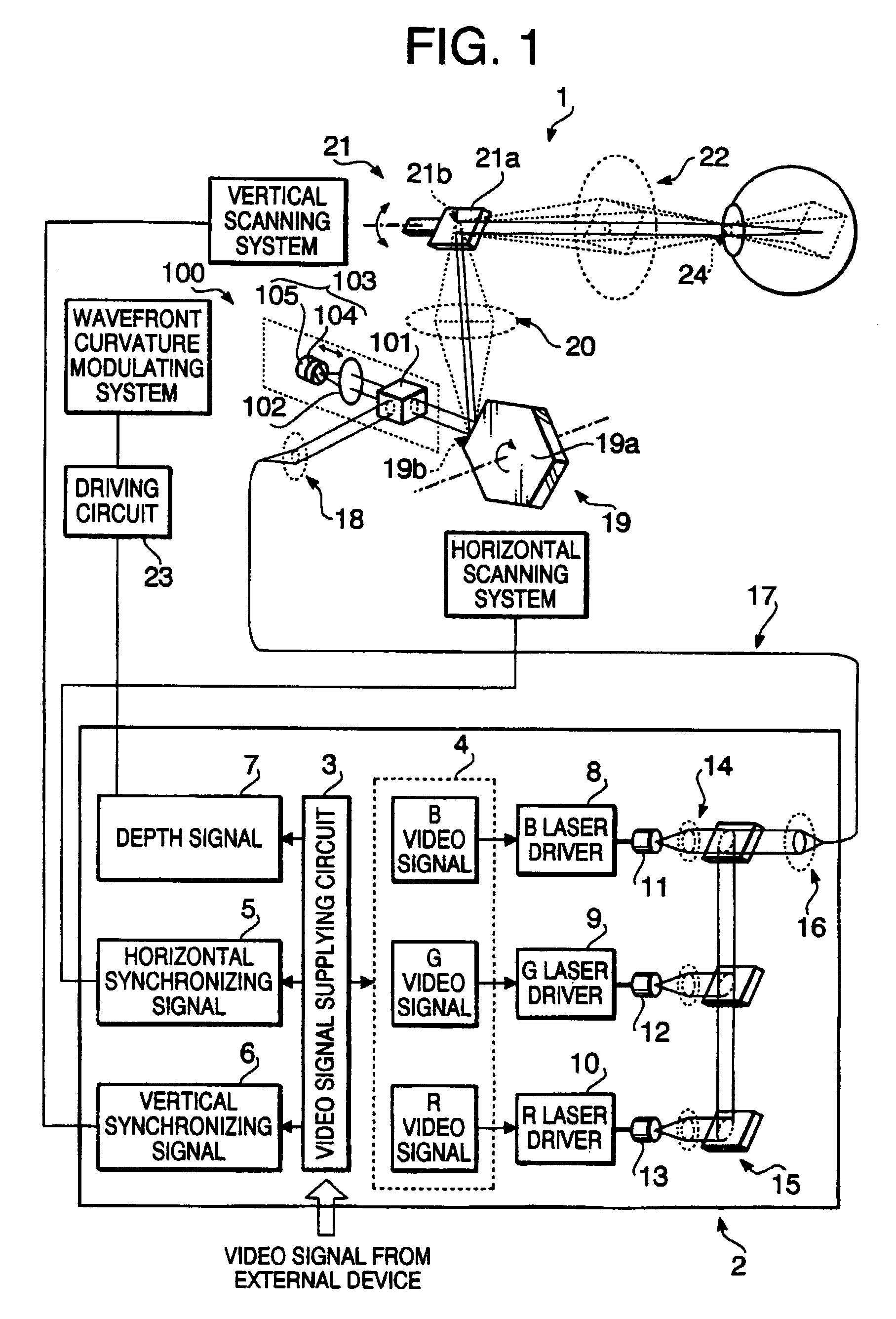
[0094]Firstly, the relationship for the retinal image scanning display device 1 according to the first embodiment will be described with referenced to FIGS. 1 and 4 through 7.
[0095]FIGS. 4A and 4B show a timing chart when the modulating frequency of the wavefront curvature is half a frequency of the vertical synchronizing signal. FIG. 5 shows two images, which have different wavefront curvatures a and b and formed alternately by the modulated beam. FIG. 6 is a synthesized image 32 which is obtained by synthesizing the two images shown in FIG. 5, which have different wavefront curvatures. FIG. 7 shows depths of the two images shown in FIG. 5.
[0096]In the example shown in FIGS. 4 and 5, it is assumed that the wavefront curvature a is smaller than the wavefront curvature b. In such a case, a radius of the wavefront curvature is greater than a radius of the wavefront curvature b. For example, the radius of the wavefront curvature a is infinity and the radius of the wavefront curvature b...
second embodiment
[0109]Next, the retinal image scanning display device 1 according to the second embodiment will be described with referenced to FIGS. 1 and 8 through 10.
[0110]FIGS. 8A and 8B show a timing chart when the modulating frequency of the wavefront curvature is equal to a frequency of the vertical synchronizing signal. FIG. 9 is a synthesized image 33 which is obtained by synthesizing two images, which have different wavefront curvatures. FIG. 10 shows depths of the synthesized image.
[0111]If the period of the wavefront modulation applied by the wavefront curvature modulating system 100 is set to be equal to or less than the period of the vertical synchronizing signal 6, an image which includes portions having different wavelength curvatures can be formed.
[0112]In particular, if the period of the wavefront curvature modulation applied by the wavefront curvature modulating system 100 is equal to the period of the vertical scanning system 21, at every period of the vertical synchronizing sig...
third embodiment
[0119]Next, the retinal image scanning display device 1 according to the third embodiment will be described with referenced to FIGS. 1 and 11 through 14.
[0120]FIGS. 11A through 11C show a timing chart showing a relationship among the modulating frequency of the wavefront curvature, horizontal synchronizing signal 5 and the vertical synchronizing signal 6. FIGS. 12A and 12B show a timing chart indicating a relationship between the wavefront curvature and the horizontal synchronizing signal 5 at about timing T1 a indicated in FIG. 11. FIG. 13 shows a synthesized image 34 which has different wavefront curvatures in vertical and horizontal directions. FIG. 14 shows arrangement of portions of the synthesized image in the depth direction.
[0121]If the period of the wavefront modulation applied by the wavefront curvature modulating system 100 is set to be equal to or less than the period of the horizontal synchronizing signal 5, an image including portions having different wavelength curvat...
PUM
 Abstract
Description
Claims
Application Information
 - R&D
- Intellectual Property
- Life Sciences
- Materials
- Tech Scout
- Unparalleled Data Quality
- Higher Quality Content
- 60% Fewer Hallucinations
Browse by: Latest US Patents, China's latest patents, Technical Efficacy Thesaurus, Application Domain, Technology Topic, Popular Technical Reports.
© 2025 PatSnap. All rights reserved.Legal|Privacy policy|Modern Slavery Act Transparency Statement|Sitemap|About US| Contact US: help@patsnap.com