
Multi-cyclone dust separator

a dust separator and multi-cyclone technology, applied in the direction of separation processes, vortex flow apparatus, colloidal chemistry, etc., can solve the problems of limited suction efficiency, short lifespan of conventional dust bags, and increase in the number or volume of second cyclone chambers, so as to improve dust-suction efficiency

Inactive Publication Date: 2009-02-24
SAMSUNG GWANGJU ELECTRONICS CO LTD
View PDF6 Cites 75 Cited by
  • Summary
  • Abstract
  • Description
  • Claims
  • Application Information

AI Technical Summary

Benefits of technology

This configuration enhances dust suction efficiency and increases the volume of the second dust receptacle, allowing for more effective dust separation and collection without interfering with the air induction path, thereby improving overall performance.

Problems solved by technology

Such a cyclone dust separator is nowadays widespread since it is nearly permanent, whereas a conventional dust bag has a relatively short lifespan.
However, according to the conventional multi-cyclone dust separator by the present applicant, since an air induction path that guides the air into the first cyclone chamber is formed necessarily through the circumference of the first cyclone chamber, the second cyclone chambers formed on the circumference of the first cyclone chamber cannot be overlappingly formed with the air induction path.
That is, the second cyclone chambers can be formed in the rest space after forming the air induction path and therefore, increase in the number or volume of the second cyclone chambers, for better suction efficiency, is restricted.

Method used


Image

  • Multi-cyclone dust separator
  • Multi-cyclone dust separator
  • Multi-cyclone dust separator

Examples


Embodiment Construction

[0019]Hereinafter, certain embodiments of the present invention will be described in detail with reference to the accompanying drawing figures.

[0020]In the following description, same drawing reference numerals are used for the same elements even in different drawings. The matters defined in the description such as a detailed construction and elements are nothing but the ones provided to assist in a comprehensive understanding of the invention. Thus, it is apparent that the present invention can be carried out without those defined matters. Also, well-known functions or constructions are not described in detail since they would obscure the invention in unnecessary detail.

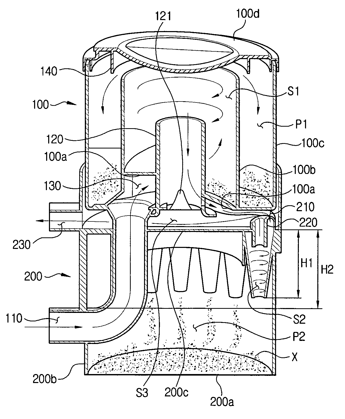
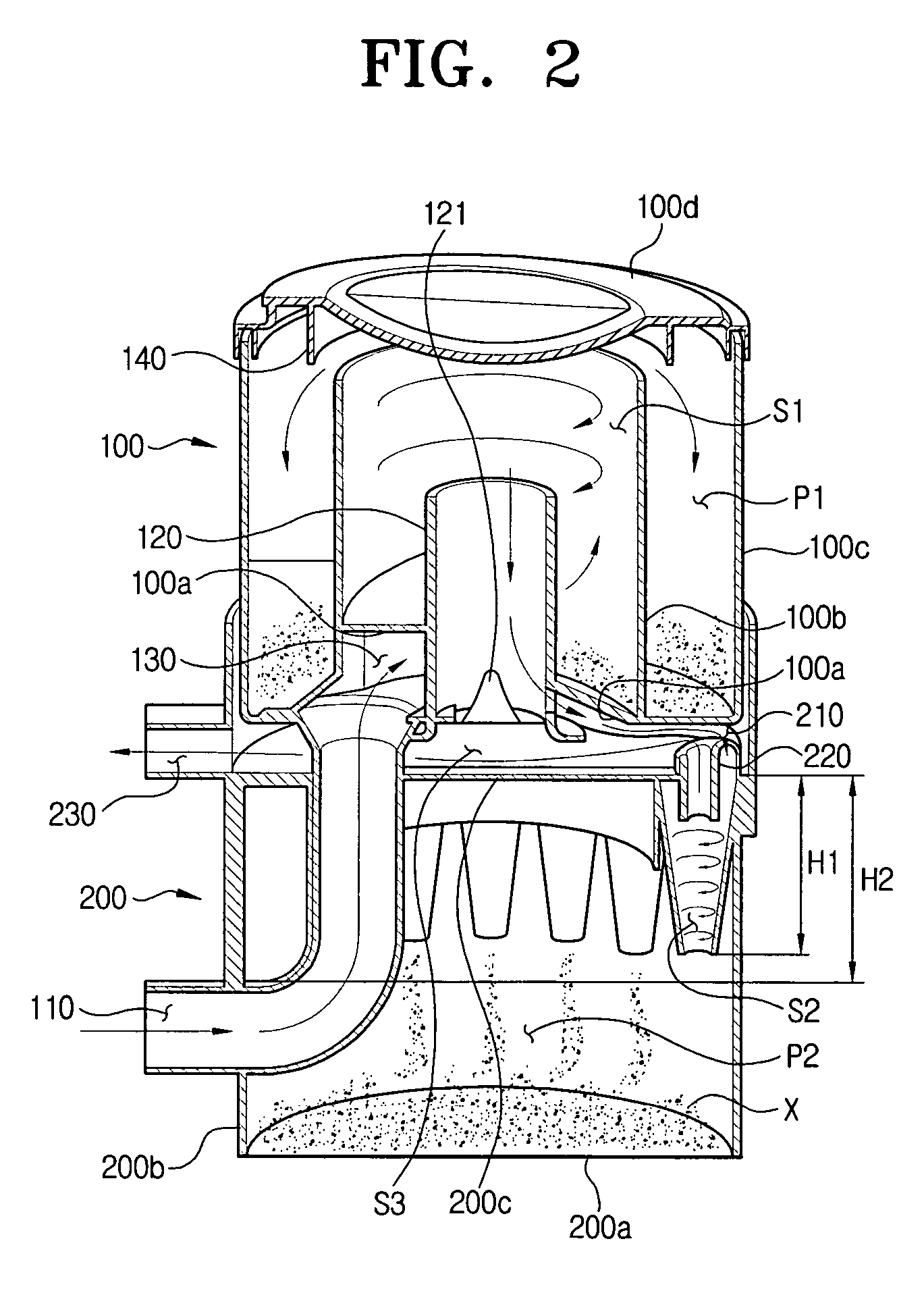
[0021]In FIG. 2, illustration of second cyclones are partly omitted for conciseness. Arrows in the drawings denote air flow and ‘X’ denotes dust.

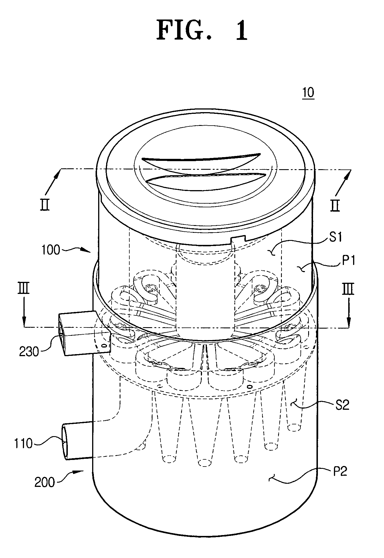
[0022]Referring to FIGS. 1 and 2, a multi-cyclone dust separator 10 comprises a first cyclone unit 100 at an upper part and a second cyclone unit 200 at a lower part.

[0023]...


PUM

PropertyMeasurementUnit
circumferenceaaaaaaaaaa
centrifugal forceaaaaaaaaaa
dust suction efficiencyaaaaaaaaaa

Abstract

A multi-cyclone dust separator according to an embodiment of the present invention comprises a first cyclone unit having a first cyclone chamber and a first dust receptacle enclosing a circumference of the first cyclone chamber; and a second cyclone unit disposed below the first cyclone unit and having a plurality of second cyclone chambers and a second dust receptacle disposed under the second cyclone chambers to collect dust.

Description

CROSS-REFERENCE TO RELATED APPLICATIONS[0001]This application claims the benefit of U.S. Provisional Application No. 60 / 666,144 filed on Mar. 29, 2005 in the United States Patent and Trademark Office, and Korean Patent Application No. 2005-37548 filed on May 4, 2005 in the Korean Intellectual Property Office, the entire disclosures of which are incorporated herein by reference.BACKGROUND OF THE INVENTION[0002]1. Field of the Invention[0003]The present invention relates to a multi-cyclone dust separator.[0004]2. Description of the Related Art[0005]Generally, a cyclone dust separator separates dust and dirt from air using a centrifugal force and then discharges the air to the outside while collecting the dust and dirt in a dedicated dust collecting chamber. Such a cyclone dust separator is nowadays widespread since it is nearly permanent, whereas a conventional dust bag has a relatively short lifespan. In order to enhance dust suction efficiency of the cyclone dust separator, a multi-...

Claims


Application Information

Patent Timeline
Patent Type & Authority Patents(United States)
IPC IPC(8): B01D45/12
CPCA47L9/1625A47L9/1641A47L9/165A47L9/1683B01D45/16B04C5/24B04C5/26Y10S55/03B01D45/12
Inventor OH, JANG-KEUNHAN, JUNG-GYUN
Owner SAMSUNG GWANGJU ELECTRONICS CO LTD
Learn More