
Shutter mechanism of automated-teller machine

a technology shutter mechanism, which is applied in the direction of automatic teller machine, atm details, instruments, etc., can solve the problems of increased failure frequency, complicated structure of the whole system, increased production cost, etc., and achieves the effect of reducing production cost, reducing production cost, and simplifying structur

Active Publication Date: 2009-02-24
NAUTILUS HYOSUNG
View PDF4 Cites 2 Cited by
  • Summary
  • Abstract
  • Description
  • Claims
  • Application Information

AI Technical Summary

Benefits of technology

"The present invention provides a shutter mechanism for an automated-teller machine that can simultaneously open and close the shutter using a single driving source. This simplifies the structure and reduces production costs, while also preventing interference during shutter closure and reducing the likelihood of damage or malfunction. The mechanism includes a main body with a frame, a sliding shutter, a protrusion, and a fixing member, an opening / closing means, a locking unit, and a driving unit. The opening / closing unit has a first operation member and a second protrusion, while the locking unit has a second operation member and a catching step. The driving unit includes a motor and a cam."

Problems solved by technology

That is, these separate driving power sources lead to a complicated structure of the whole system, an increase in failure frequency, and increased production costs.

Method used


Image

  • Shutter mechanism of automated-teller machine
  • Shutter mechanism of automated-teller machine
  • Shutter mechanism of automated-teller machine

Examples


Embodiment Construction

[0016]Hereinafter, a preferred embodiment of the invention will be described in detail with reference to the accompanying drawings.

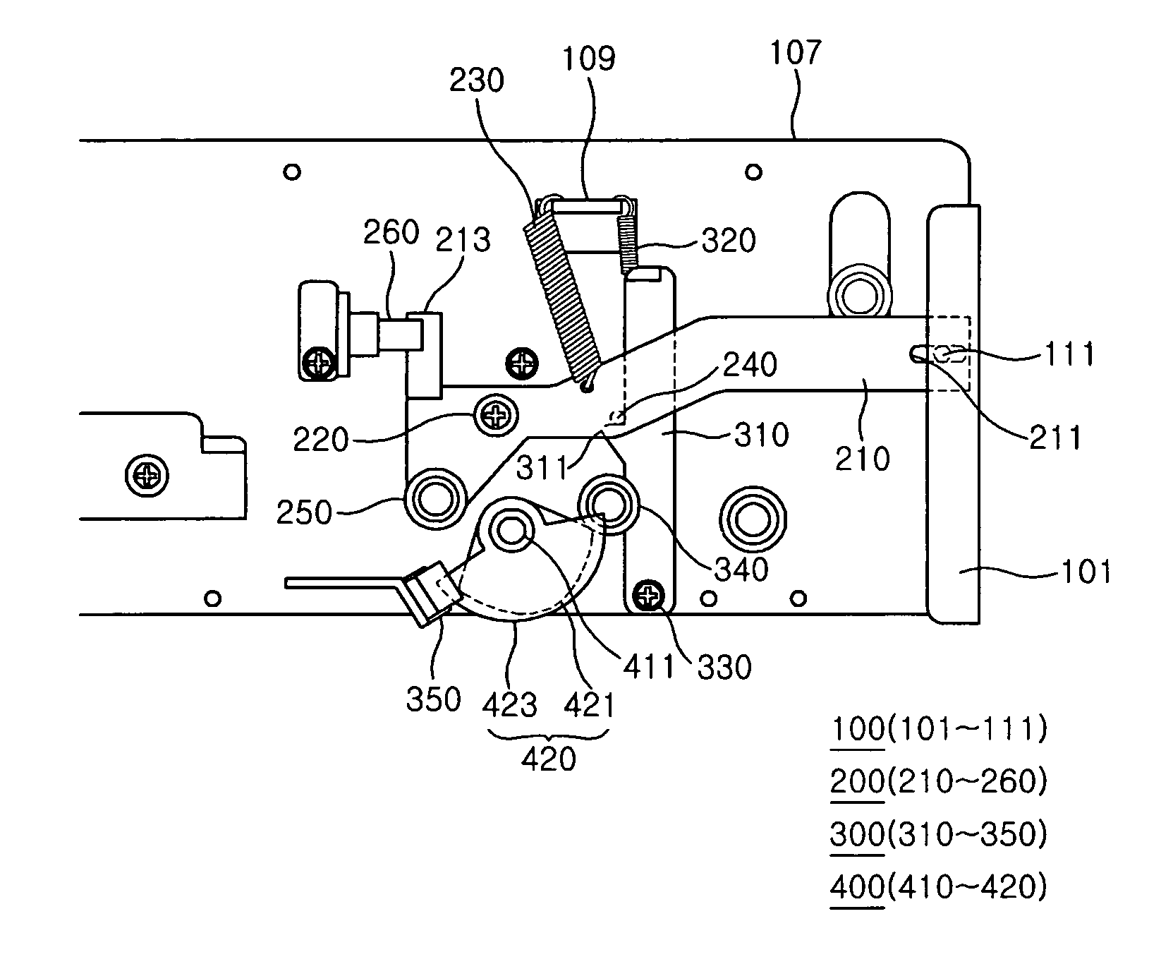
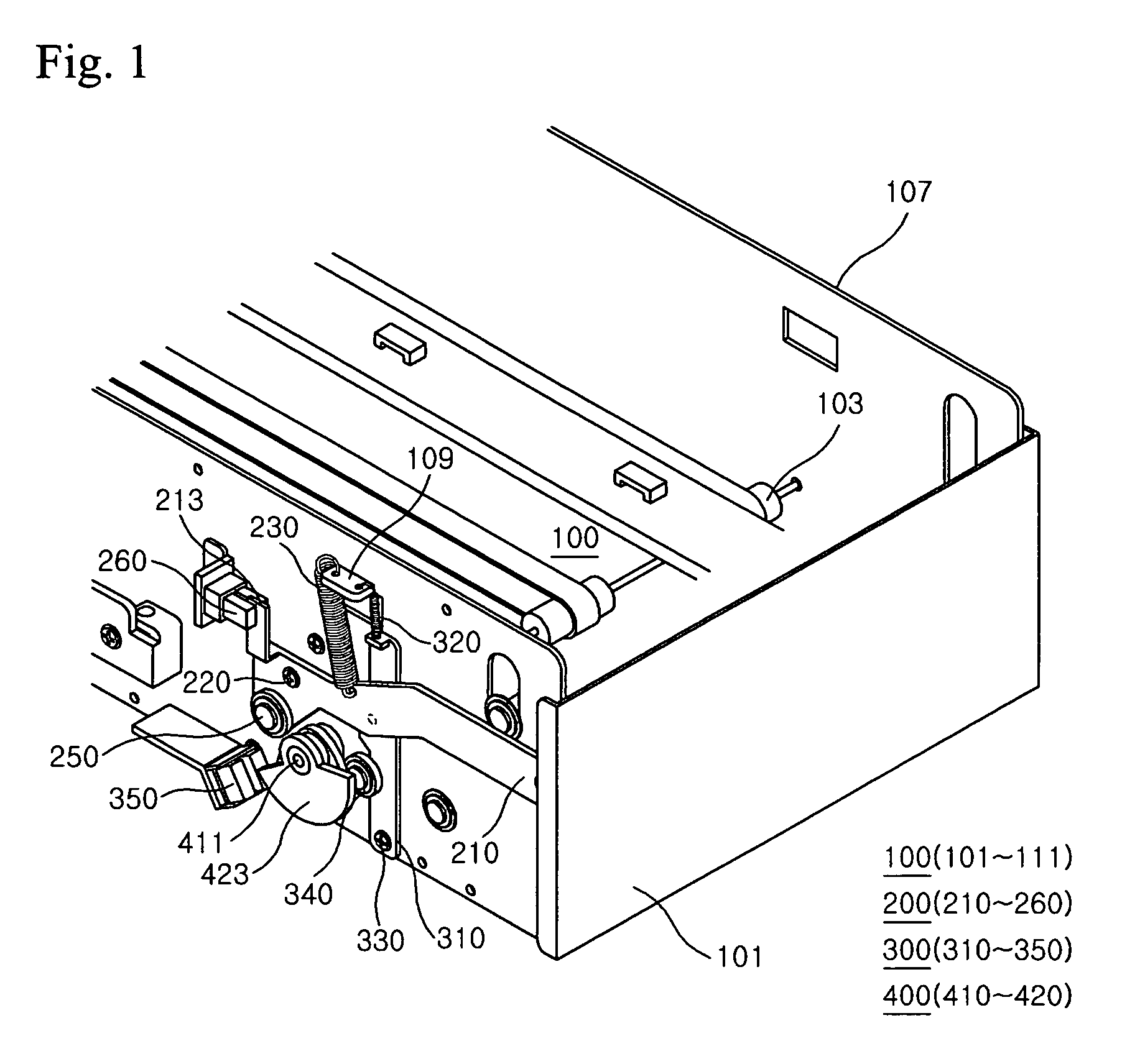
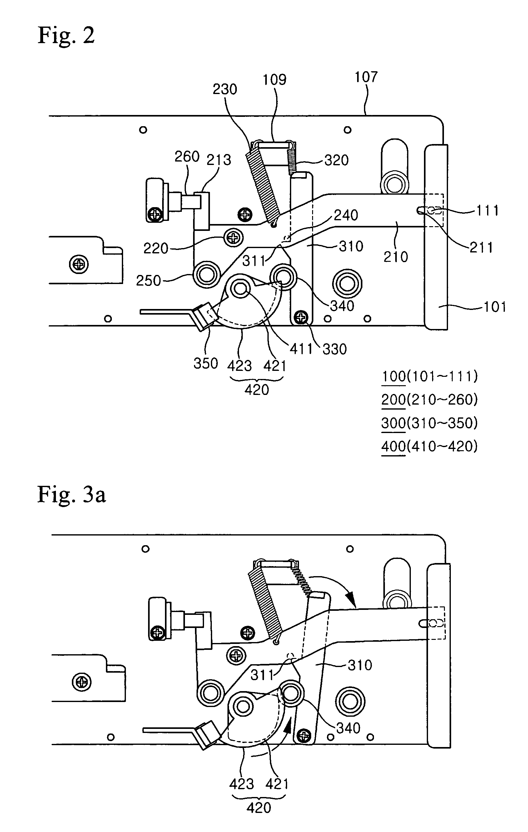
[0017]FIG. 1 is a perspective view of a shutter mechanism of an automated-teller machine according to the invention, and FIG. 2 is a side view of the shutter mechanism of an automated-teller machine according to the invention.

[0018]The shutter mechanism of the invention comprises a main body 100 including a shutter 101, an opening / closing unit 200 for opening and closing the shutter 101 in response to an external signal, a locking unit 300 for preventing the shutter 101 from being opened by an external force without any separate signal, and a driving unit 400 for simultaneously operating the opening / closing unit 200 and the locking unit 300.

[0019]In the following description, the term “front” or “forward” is defined as indicating a side where the shutter 101 is provided in the main body 100, and the term “rear” or “backward” is defined as indicating an o...


PUM


Abstract

A shutter mechanism of an automated-teller machine according to the present invention comprises a main body including a frame, a shutter slidably coupled to a front side of the frame, a first protrusion protruding inward on an inner lateral surface of the shutter, and a fixing member protruding on a side surface of the frame; an opening / closing means for opening and closing the shutter in response to an external signal; a locking unit for preventing the shutter from being opened by an external force without a separate signal; and a driving unit for simultaneously operating the opening / closing unit and the locking unit. Therefore, the present invention provides a shutter mechanism of an automated-teller machine, wherein a shutter-opening / closing operation and a shutter-locking operation can be simultaneously carried out using a single driving source, thereby simplifying its structure and also reducing its production costs, and interference that may occur while the shutter is being closed does not impose a load on the driving source, thereby preventing damage to and malfunction of the mechanism, reducing a failure rate and also maintaining a smooth operational state.

Description

BACKGROUND OF THE INVENTION[0001]1. Field of the Invention[0002]The present invention relates to a shutter mechanism of an automated-teller machine, and more particularly, to a shutter mechanism of an automated-teller machine, which has a simplified structure for opening and closing a shutter that is to be opened when a bank note is deposited or withdrawn, and is provided with a means capable of coping with a case where interference occurs during a shutter-closing process.[0003]2. Description of the Related Art[0004]In general, an automated-teller machine is used by banks or other financial institutions in order to provide a convenient banking service to their customers. The automated-teller machine is installed in convenience stores or public places in addition to the premises of the banks or financial institutions, and is configured such that customers can deposit or withdraw cash money conveniently whenever needed, using a cash card or a credit card.[0005]Recently, such an automa...

Claims


Application Information

Patent Timeline
Patent Type & Authority Patents(United States)
IPC IPC(8): G07F19/00G06F7/08
CPCG07F19/20G07F19/205G07D2211/00G07F19/201
Inventor AHN, JIN HYUKLEE, WON JOONLEE, DONG SIKYOON, YOU HOON
Owner NAUTILUS HYOSUNG
Learn More