Optical communication system having an antiresonant dispersion map suppressing four wave mixing and cross phase modulation

a technology of optical transmission system and dispersion map, which is applied in the field of optical transmission system dispersion map for undersea optical transmission system, can solve the problems of power transfer out of the signal into unwanted wavelengths, fiber loss in such systems in the range of about 0.20 to 0.25 db/km, and inability to achieve the effect of enhancing these processes, suppressing nonlinear interactions, and sound signal temporal fidelity

Inactive Publication Date: 2009-02-17
HUAWEI MARINE NETWORKS CO LTD
View PDF6 Cites 2 Cited by
  • Summary
  • Abstract
  • Description
  • Claims
  • Application Information

AI Technical Summary

Benefits of technology

[0008]The principle of using large local values of dispersion to suppress nonlinear interactions and concatenating segments of such fiber with opposite delay values to ensure temporal fidelity of the signal is sound. However the transmission line is a periodic structure; the regularly spaced amplifiers give rise to periodic fluctuations in the signal energy. This introduces an asymmetry to the FWM and XPM between signal

Problems solved by technology

Fibers in such systems typically have losses in the range of about 0.20 to 0.25 dB / km.
In particular transmission performance is limited by a number of phenomena, including accumulation of amplified spontaneous emission (ASE) noise, dispersion, and a nonlinear component to the refractive index of the fiber.
For amplitude modulated digital signals temporal distortions due either to dispersion or Kerr effect are a significant contributing factor to the bit error rate (BER).
The result is the transfer of power out of the signal and into unwanted wavelengths.
As a result of the interaction, energy will be transferred from one signal to another leading to waveform distortions.
Conversely if the signal propagates at a wavelength for which the dispersion is large then there is a large phase mismatch (i.e., a group velocity difference) between the signal and noise or two adjacent signal channels, which greatly reduces the efficiency of four wave mixing.
However, large values of dispersion result in increased inter-symbol interference due to the temporal spreading of the signal.
If the fiber has non-zero chromatic dispersion, then pulse spreading results, with attendant intersymbol interference.
On the other hand, if chromatic dispersion is zero everywhere along the transmission fiber then non-linear effects such as four-wave-mixing will cause power transfers between signal channels as well as between signal and noise.
In either case the result is a degradation in system performance.
So despite the use of dispersion maps to suppress nonlinear interactions, FWM and XPM can still be problematic.

Method used


Image

  • Optical communication system having an antiresonant dispersion map suppressing four wave mixing and cross phase modulation
  • Optical communication system having an antiresonant dispersion map suppressing four wave mixing and cross phase modulation
  • Optical communication system having an antiresonant dispersion map suppressing four wave mixing and cross phase modulation

Examples


Embodiment Construction

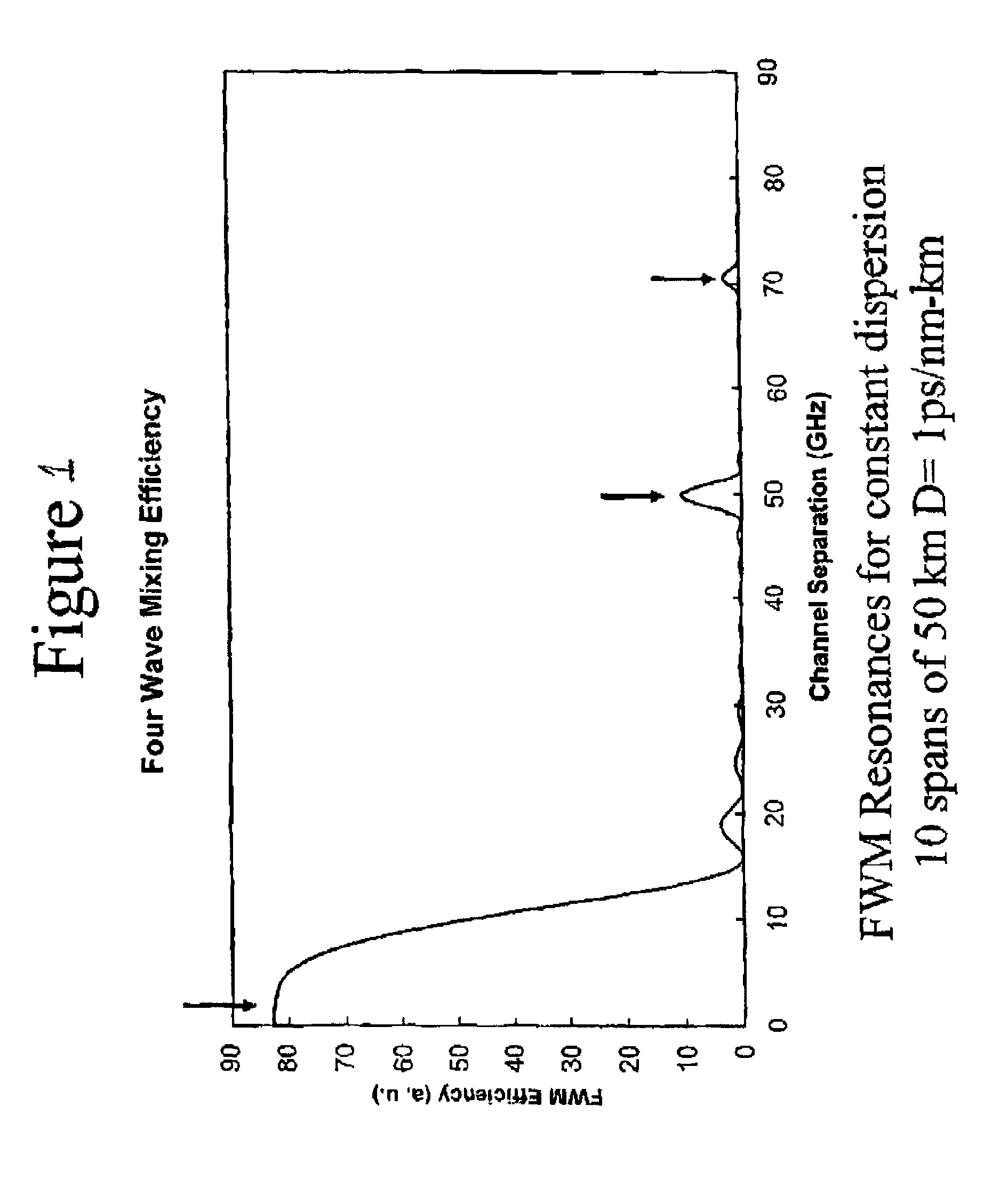
Resonant Four Wave Mixing for Constant Dispersion

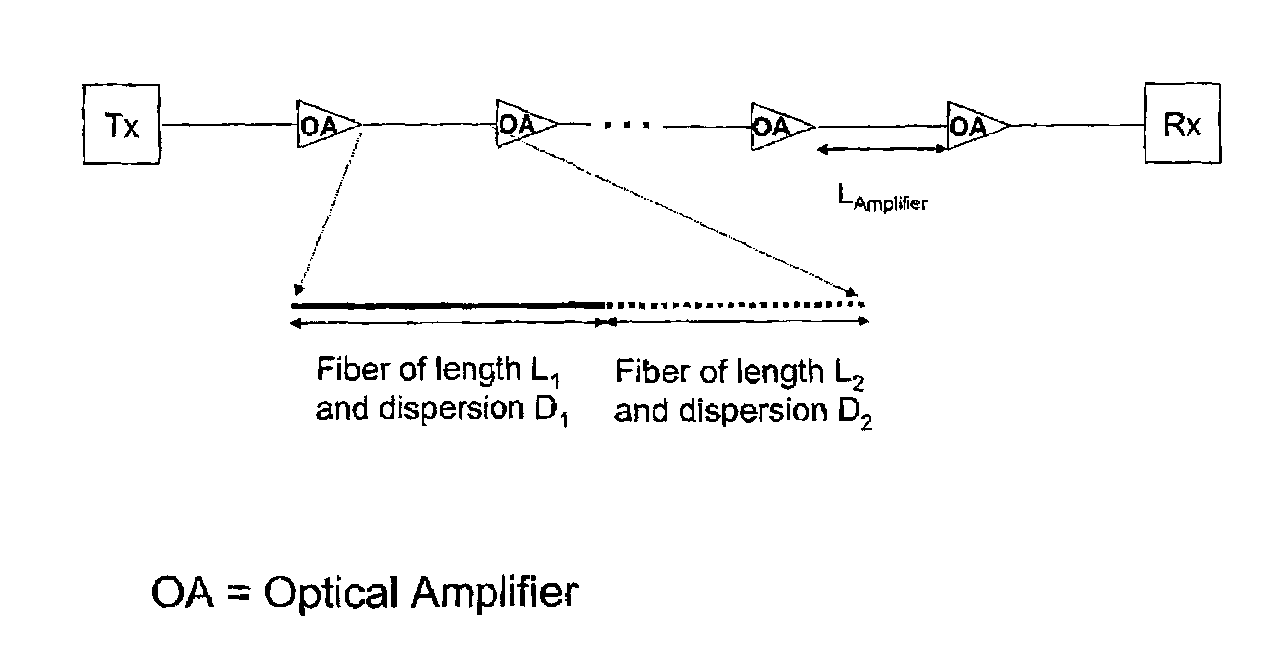
[0023]Recent work, both theoretical and experimental, has demonstrated that the phenomenon of resonant four wave mixing in transmission lines can be greatly enhanced by the periodic fluctuations of signalintensity due to loss in the fiber and gain in the amplifiers. (See, for example, “Pseudo-phase-matched four wave mixing in soliton wavelength-division multiplexing transmission” P. V. Mamyshev and L. F. Mollenauer Optics Letters Vol. 21 No.6 Mar. 15, 1996; “Energy Transfers and Frequency Shifts from Three Soliton Collisions in a Multiplexed Line with Periodic Amplification” S. G. Evangelides and J. P. Gordon Journal of Lightwave Technology Vol. 14 No. 7 July 1996; “Phase-mismatching characteristic of four-wave mixing in fiber lines with multistage optical amplifiers” K. Inoue Optics Letters Vol. 17, No. 11 Jun. 1, 1992). In resonant four wave mixing, the periodicity of gain and loss along the transmission line serves to phase match (...


PUM


Abstract

An optical communication system transmitting a plurality of channel wavelengths is provided. The system includes a transmitter unit, a receiver unit, and an optical transmission path interconnecting the transmitter and receiver units. The transmission path has a concatonation of optical fibers defining a dispersion map such that each of the channel wavelengths are located at FMX and XPM antiresonances at which FWM and XPM are suppressed.

Description

STATEMENT OF RELATED APPLICATION[0001]This application claims the benefit of priority to U.S. Provisional Patent Application Ser. No. 60 / 404,617, filed Aug. 20, 2002 and entitled “The Antiresonant Dispersion Map.”FIELD OF THE INVENTION[0002]The present invention relates generally to optical transmission systems, and more particularly to a dispersion map for an undersea optical transmission system.BACKGROUND OF THE INVENTION[0003]The introduction of multigigabit, multiwavelength optical communication systems operating over long distances (e.g., transoceanic) and high average powers has resulted in the exploration of fiber designs that can minimize signal degradation. Fibers in such systems typically have losses in the range of about 0.20 to 0.25 dB / km. To increase bandwidth, fibers need to be redesigned to reduce a number of nonlinear and polarization effects that become increasingly important at high bit rates and high powers. In particular transmission performance is limited by a n...

Claims


Application Information

Patent Timeline
IPC IPC(8): H04B10/12H04B10/18
CPCH04B10/2557H04B10/2563
Inventor EVANGELIDES, JR., STEPHEN G.
Owner HUAWEI MARINE NETWORKS CO LTD
Why Eureka
Try Eureka