
Touch screen control

a technology of touch screen and control device, which is applied in the field of visual display units, can solve the problems of increasing the size, weight and cost of such cameras, and the difficulty of users to quickly and accurately vary the image properties, so as to increase/decrease increase and reduce the value of the selected image property

Active Publication Date: 2009-02-10
THERMOTEKNIX SYSTEMS LTD
View PDF7 Cites 59 Cited by
  • Summary
  • Abstract
  • Description
  • Claims
  • Application Information

AI Technical Summary

Benefits of technology

"The present invention provides a digital imaging device with a touch-sensitive display screen that allows users to capture and display images while easily controlling various image properties using icons. The icons are displayed on the screen and users can touch or tap on them to control the image properties, such as brightness, color balance, and contrast. The device can also display a plurality of icons on the screen, each corresponding to a different image property, and users can selectively control the value of the property by touching the corresponding icon. The device can also display a control icon with multiple portions, each portion operative to vary the image property in a different manner. Overall, the invention provides a simple and accurate means for users to control the image properties they desire."

Problems solved by technology

Use of conventional control means to vary image properties can however be less than convenient for a user.
In particular, if the user wishes to select one of a number of properties to vary or wishes to vary only one end of a range of an image property, then unless the device is provided with a large number of individual switches it is difficult for a user to rapidly and accurately vary the image properties.
Additionally, provision of a large number of mechanical switches adds significantly to the size, weight, and cost of such a camera whilst also significantly detracting from the ease of carriage and reliability for such a camera, particularly if the mechanical switches are adapted to function in a harsh environment.

Method used


Image

  • Touch screen control
  • Touch screen control

Examples


Embodiment Construction

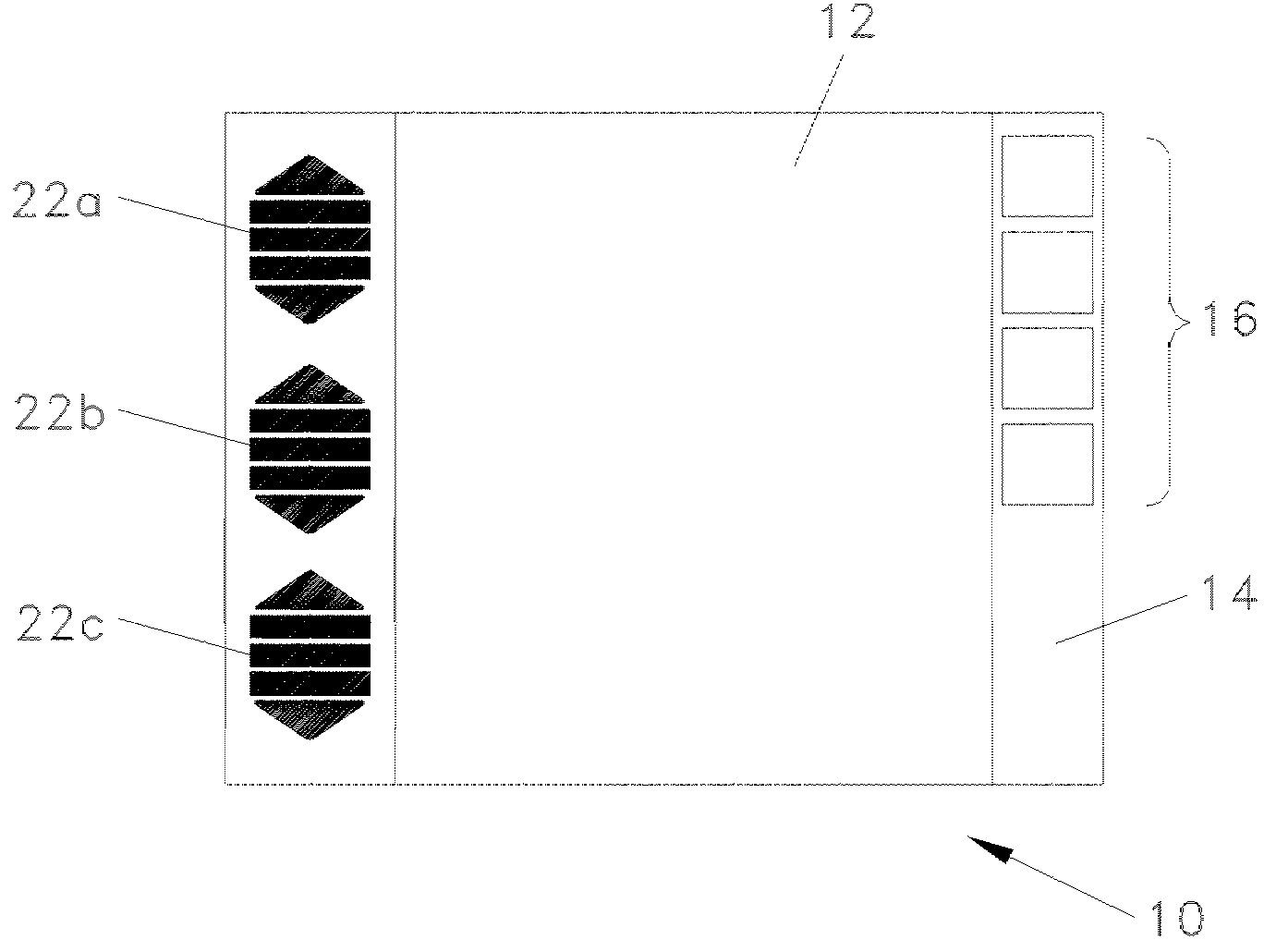
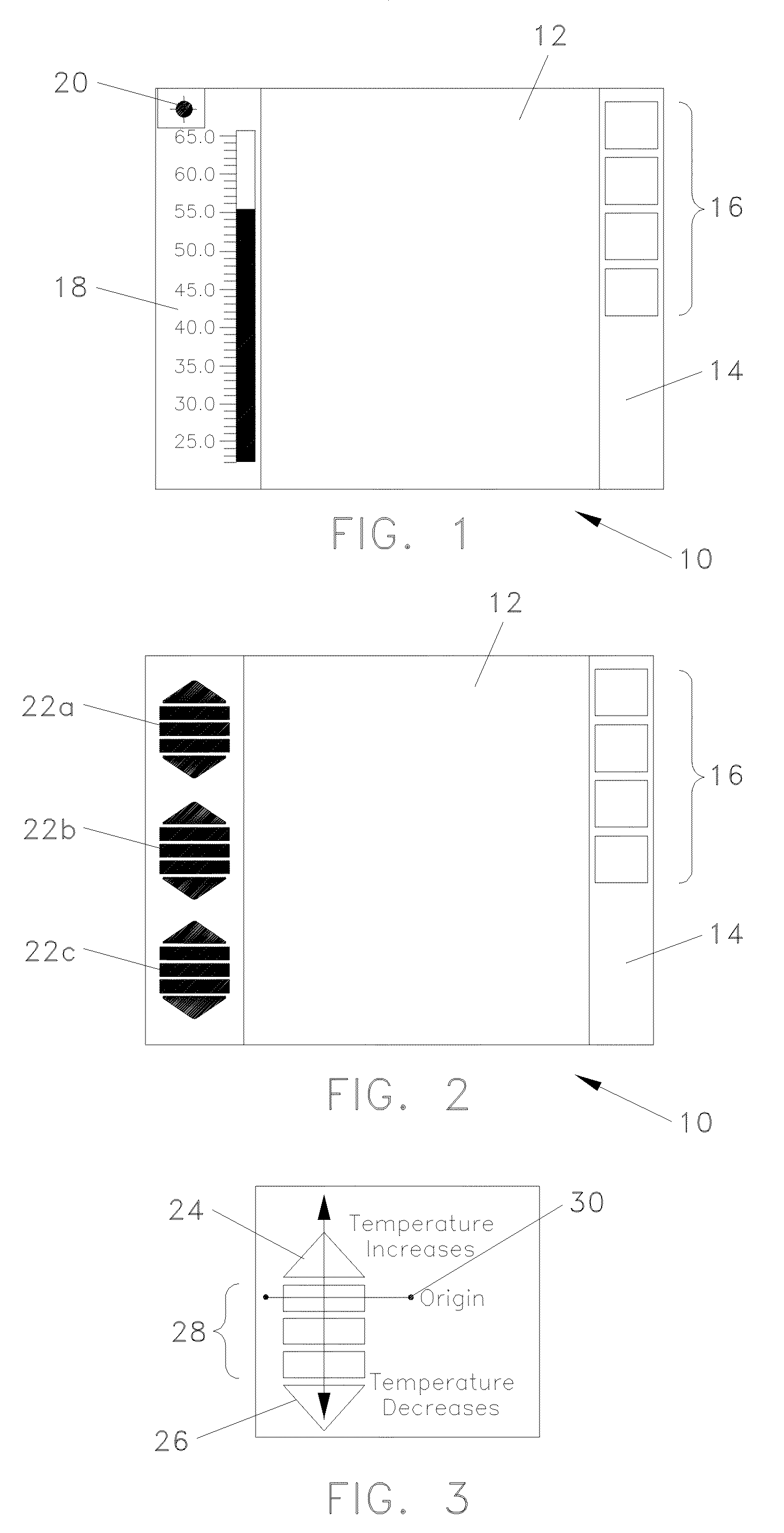
[0026]Referring now to FIG. 1, a touch sensitive display screen 10 for a digital imaging device is shown. The screen 10 displays an image 12 captured by the imaging device. Along one side of the screen is a toolbar 14 upon which is provided a plurality of individual icons 16. The icons 16 represent particular control functions that may be selected by a user. Examples of such control functions represented by the icons 16 include but are not limited to save, send, retrieve or discard image; rotate, reflect, crop, resize or edit image; compare images; process image (e.g. sharpen, blur, emboss, edge detect, pixelise, apply filter or similar); or vary image properties (e.g. brightness, colour balance, colour depth, contrast, convert to greyscale / black and white, effective surface temperature displayed (for infrared images) or similar). The user can select icons by touching the screen either directly or more preferably by tapping the screen with a suitable implement such as a pen, a stylu...


PUM


Abstract

A digital imaging device is provided with a touch sensitive display screen 10. The screen 10 displays an image 12 captured by the imaging device. Along one side of the screen is a toolbar 14 upon which is provided a plurality of individual icons 16. The icons 16 represent particular control functions that may be selected by a user. Examples of such control functions represented by the icons 16 include but are not limited to save, send, retrieve or discard image; rotate, reflect, crop, resize or edit image; compare images; process image (e.g. sharpen, blur, emboss, edge detect, pixelise, apply filter or similar); or vary image properties (e.g. brightness, colour balance, colour depth, contrast, convert to greyscale / black and white, effective surface temperature displayed (for infrared images) or similar). The user can select icons by touching the screen either directly or more preferably by tapping the screen with a suitable implement such as a pen, a stylus or similar. Once a user has selected an icon, further icons may be displayed on the screen to allow the user to operate the selected function as desired.

Description

TECHNICAL FIELD[0001]The present invention relates to a visual display unit wherein image properties may be adjusted using suitable control means and more particularly to a digital imaging device incorporating such a visual display unit.BACKGROUND[0002]Digital imaging devices such as digital cameras typically comprise means for capturing an image, means for storing the captured image, and means for displaying the captured image to a user. The means for displaying the image to the user is conventionally a display screen such as a liquid crystal display screen or similar.[0003]It is often desirable to process the displayed image or alter the properties of the displayed image (or the properties of the captured image) to allow a user to see a feature or features displayed in the image more clearly. Typically, the adjustable properties may include brightness, colour balance, contrast etc.[0004]In a particular example, infrared sensing digital cameras are used to monitor the effective sur...

Claims


Application Information

Patent Timeline
Patent Type & Authority Patents(United States)
IPC IPC(8): G09G5/00G06F3/033G06F3/048
CPCG06F3/04845G06F3/04886H04N5/23293H04N23/633H04N23/632
Inventor SALISBURY, RICHARDHAIGH, PETER
Owner THERMOTEKNIX SYSTEMS LTD
Learn More