
Battery optimization system and method of use

a battery optimization and optimization system technology, applied in the direction of battery/fuel cell control arrangement, electric devices, transportation and packaging, etc., can solve the problems of resistive heat loss of all the charging current being sent to the bypassed cell, battery capacity can be considerable, and the battery is limited in its ability to be charged as well as discharged, so as to maximize the battery capacity and minimize the effect of electrical components

Inactive Publication Date: 2009-02-10
TIKHONOV VICTOR
View PDF7 Cites 141 Cited by
  • Summary
  • Abstract
  • Description
  • Claims
  • Application Information

AI Technical Summary

Benefits of technology

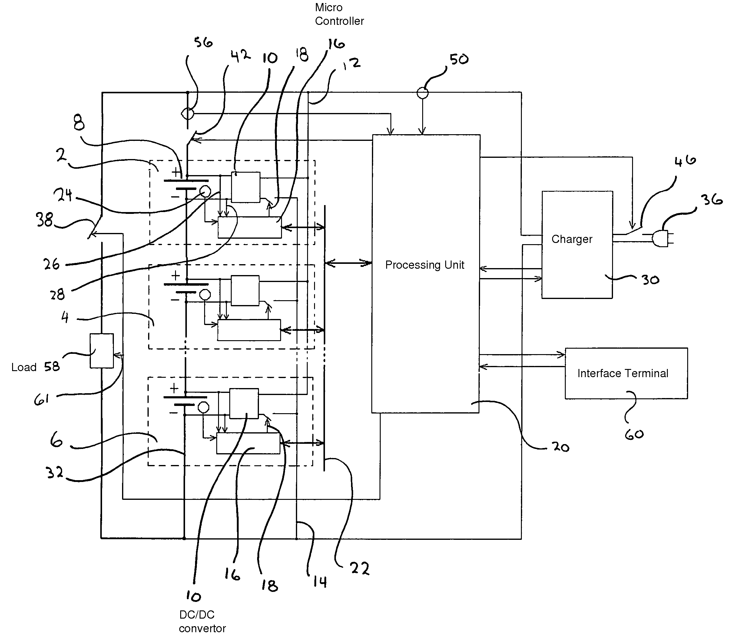
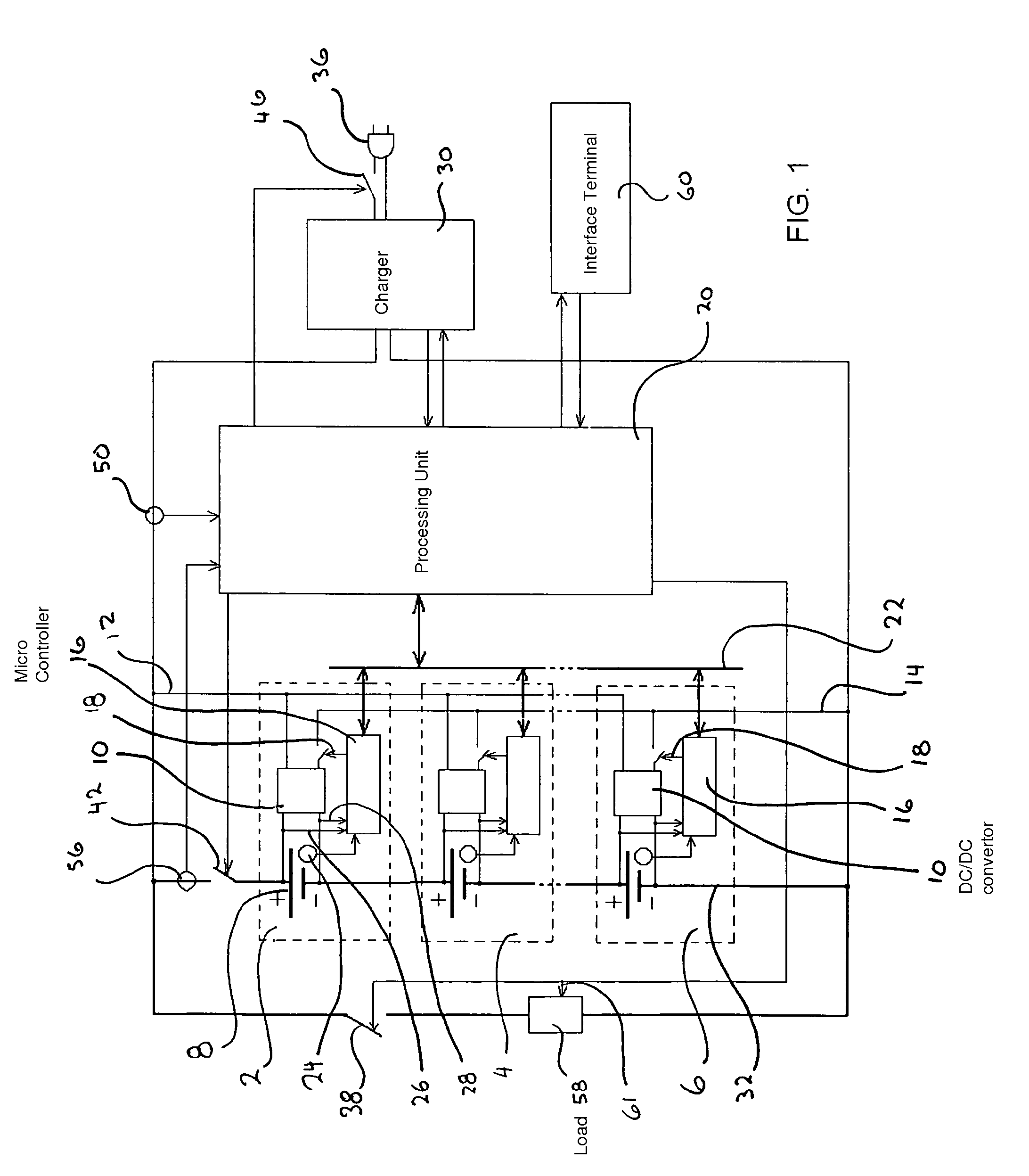
[0012]The general purpose of the present invention, which will be described subsequently in greater detail, is to provide an economical, battery optimization or management system that will maximize battery capacity while minimizing electrical components.
[0014]In accordance with the invention, an object of the present invention is to provide an improved battery optimization system that does not resistively shunt undesired electricity to return individual cells to a more optimally balanced state with respect to the battery's other cells.
[0016]It is a further object of this invention to provide an improved battery optimization system that maximizes the capacity of a battery composed of a string of electrical storage cells by maintaining all cells at an equal state of charge with respect to each cells' own capacity.
[0017]It is another object of this invention to provide a battery optimization system that has the ability to collect, process, store and / or display / transmit data, as well as control the propulsion, charging and environmental control sub-systems preventing overdischarge, overcharge, overload over / under temperature and other dangerous conditions.

Problems solved by technology

Since charging these larger capacity batteries can take considerable time, manufacturers strive to maximize the vehicle's range.
Simply stated, the battery is limited in it's ability to be charged as well as it's ability to be discharged.
The drawback of this system is that all of the charging current being sent to the bypassed cell is lost to resistive heat.
Further, these battery management systems do not deal with equalization of the cells in the discharge mode.
Again, equalizing voltages in such cases will unproductively disturb this balance.

Method used


Image

  • Battery optimization system and method of use
  • Battery optimization system and method of use
  • Battery optimization system and method of use

Examples


Embodiment Construction

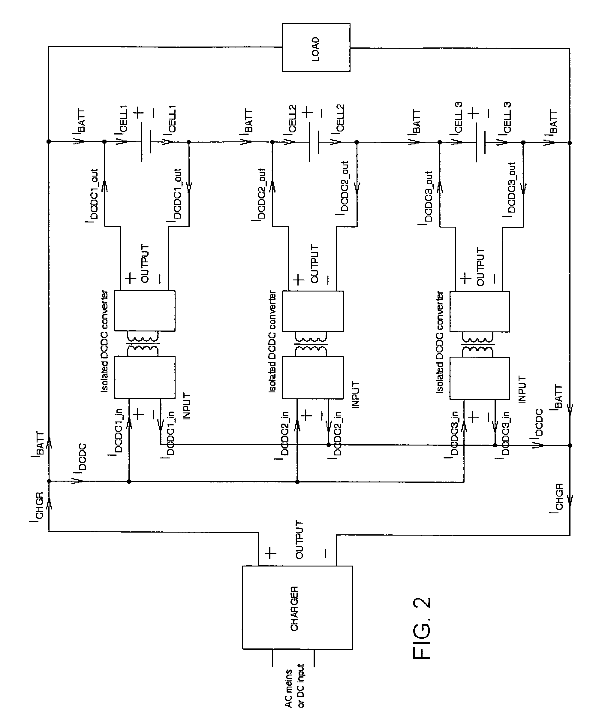
[0056]Assume that the efficiency of each DC / DC converter is 100%. (In reality the efficiency of DC / DC converters is not 100%, and a DC / DC converter never returns the same amount of energy it consumes. In Example 2 it will be shown that the DC / DC converter efficiency is not relevant to the principle of operation.) Further, assume the output of each DC / DC converter is a constant 3A current. When the converters are remotely enabled (turned on and off by the microprocessor unit), IDCDC_out=3A. Assume the voltage of each cell is 4V such that in this string of three cells the total battery voltage is 12V.

[0057]Traditionally, two methods have been used for charging this battery. In the conventional method the main charger is enabled and the DC / DC converters are not enabled. In this case IDCDC_in and IDCDC1_out will be 0A and ICHRG will simply be equal to IBATT and equal to ICELL1, or ICELL2 or ICELL3, since the current at any point of a circuit of series connected cells is the same. This m...


PUM


Abstract

The present invention relates to a microprocessor controlled battery management system that optimizes the total electrical capacity of that battery. It uses localized cell power sources that correct the capacity of the individual connected cells to achieve the maximum capacity of the battery as it acts in a synergistic series connection of cells. The microprocessor retrieves data of battery load current, cell voltage, cell temperature, and battery charger current in timed increments. Through the application of the microprocessor's algorithms, after an initial cell profiling of individual cell capacities has been performed, individual cell DC / DC converters are enabled to correct the condition of the individual cells. In this manner the battery capacity is not affected by the capacity of the weakest cell.

Description

FIELD OF THE INVENTION[0001]The present invention relates to an improved battery optimization system. More specifically, it relates to a microprocessor controlled system that retrieves incremental data updates of electrical related parameters taken from each individual cell in a battery comprised of a string of series connected cells, and manages the capacity of the individual cells in the battery. With this capacity management of each individual cell, the battery's charge capacity is maximized and the battery's overall capacity is not limited by the capacity of the weakest cell.BACKGROUND[0002]Battery capacity is extremely critical in many industrial, commercial and medical situations but specifically in electric motorized propulsion applications. Since charging these larger capacity batteries can take considerable time, manufacturers strive to maximize the vehicle's range. Maximizing battery capacity is one of the goals of the battery optimization system.[0003]A battery is a group...

Claims


Application Information

Patent Timeline
Patent Type & Authority Patents(United States)
IPC IPC(8): H02J7/00
CPCH02J7/0018B60L11/1861B60L11/1866B60L3/0046Y02T10/92B60L2210/12B60L2210/14B60L2240/545B60L2240/547B60L2240/549Y02T10/7044Y02T10/7005Y02T10/7233Y02T10/7225Y02T10/7061B60L58/14B60L58/15B60L58/16B60L58/22Y02T10/70Y02T10/72
Inventor TIKHONOV, VICTOR
Owner TIKHONOV VICTOR
Learn More