
Vascular access closure system

a vascular access and closure system technology, applied in the field of sealing apertures, can solve the problems of significant bleeding, severe bleeding from a blood vessel puncture in a substantially sized blood vessel, infection, etc., and achieve the effect of facilitating the placement of the vascular sealing device and facilitating the operation

Inactive Publication Date: 2009-02-10
TELEFLEX LIFE SCI LTD
View PDF34 Cites 119 Cited by
  • Summary
  • Abstract
  • Description
  • Claims
  • Application Information

AI Technical Summary

Benefits of technology

[0012]In one embodiment, the delivery tube further includes a handhold, and the system is also provided with a funnel / loader and a cutter to facilitate ease of operation. The flange and flexible stem are preferably constructed of a biodegradable material that has a tensile strength, rigidity, memory and other physical qualities similar to medical grade silicone.
[0013]Following completion of the primary medical procedure, the primary surgical instrument is removed and the vascular access closure system of the present invention is inserted through the same introducer that was used for the primary medical procedure. The closure system is inserted into the introducer through a loader. The loader is a funnel-like structure which both forms the flange into a folded shape adapted to facilitate placement of the vascular sealing device and protects the flange while the flange is being passed through the introducer. Once the flange has been pushed completely through the introducer and into the blood vessel lumen, it is advanced several millimeters into the blood vessel lumen. This allows the flange to unfold and return to its memory shape. Thereupon, the delivery tube is retracted and the vascular closure device is engaged against the distal end of the introducer. The introducer is retracted until the flange is flattened flush against the interior of the blood vessel wall. Once the flange is flush against the interior blood vessel wall, the introducer is slowly withdrawn from the tissue tract.

Problems solved by technology

In particular, arterial punctures, that is punctures through the wall of an artery, offer the opportunity for significant bleeding because of the relatively high pressure of blood within the artery.
Bleeding from a vessel puncture in a substantially sized blood vessel can be severe.
Because vascular access procedures are so common and because the potential complications from failing to effectively seal a vessel puncture can be severe, substantial efforts have been made to resolve the problem of plugging or sealing vessel wall punctures.
Potential problems with this approach are that the point of anchorage may be dislodged or that the filament leading to the outside of the body will provide a continuing path for pathogens creating the possibility of infection.
The requirement that the filament be secured to the body exterior adds an additional time-consuming step to the procedure.
While mostly effective, this approach typically requires more complex and expensive equipment and the success rate is dependent upon the skill of the operator of the equipment.
The challenge with these approaches is preventing the clotting induction agent or expanding hemostatic material from being introduced into the blood vessel itself.
The introduction of either agent into the general blood circulation may lead to emboli which will travel with the circulating blood and may lodge in smaller blood vessels leading to interruption of blood flow and ischemia in a remote location.
Ischemia can lead to serious consequences.
The umbrella-like structures utilized are rather bulky even in the closed state.
Further, the act of deploying the umbrella-like structure in the vessel lumen may be disadvantageous, particularly as the umbrella-like structure may disrupt the fluid flow within the vessel and thereby encourage thrombus formation.
The challenge with this approach is controlling what happens to the balloon after the puncture is sealed and, like the flat plug embodiments, keeping the balloon secure against the vessel wall while the puncture heals.

Method used


Image

  • Vascular access closure system
  • Vascular access closure system
  • Vascular access closure system

Examples


Embodiment Construction

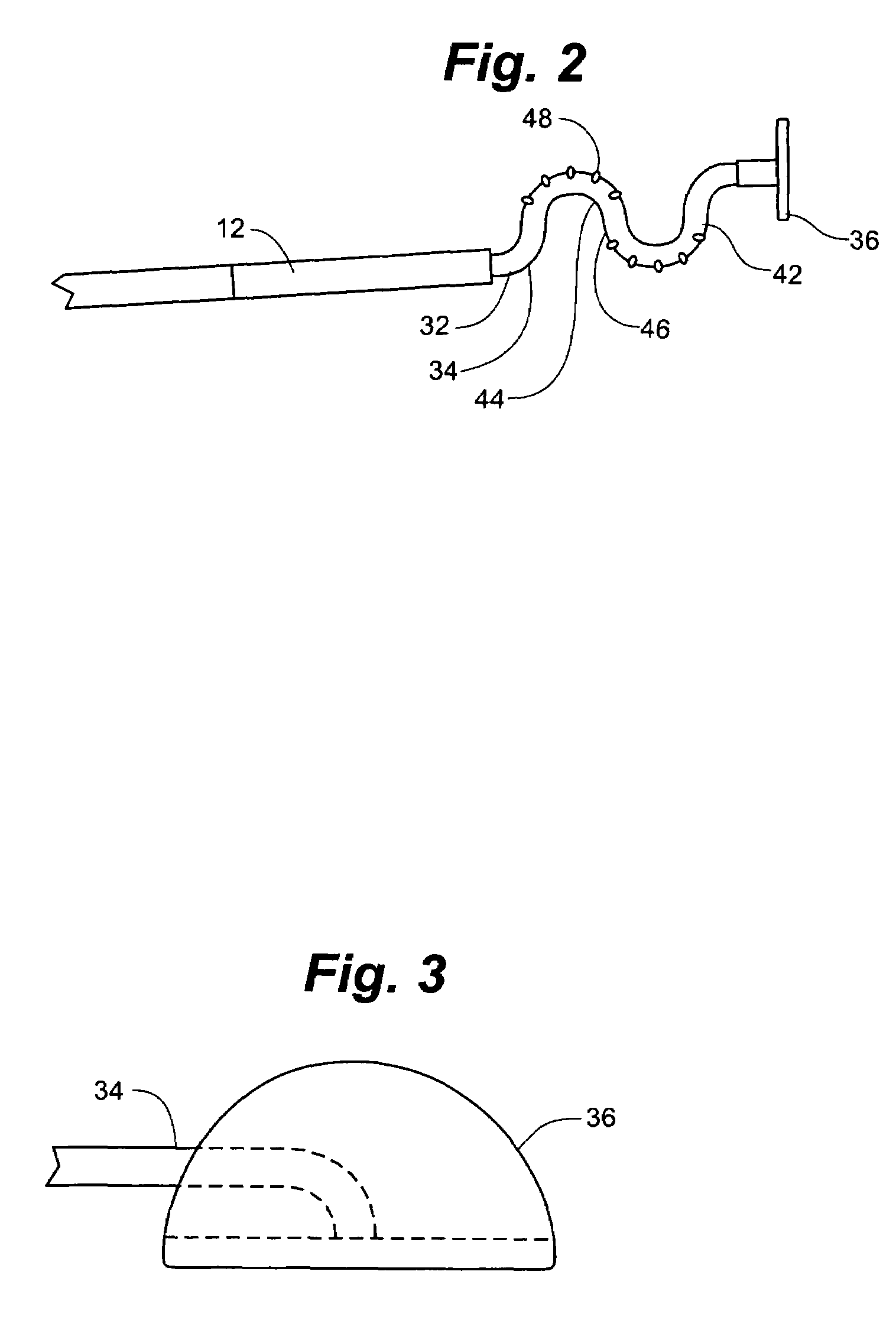
[0036]As shown in FIG. 5A, the vascular access closure system 10 of the present invention is adapted for insertion into a vessel 13, typically via a conventional introducer 11. Vascular access closure system 10 generally includes a delivery tube 12 and a vascular sealing member 14 comprised of a flexible member 32 having a flange 36 that is carried by delivery tube 12. A tissue tract 21 has a distal opening that forms a vessel puncture 17 in a vessel wall 15. The vascular access closure system 10 is utilized to seal the vessel puncture 17 created in the blood vessel wall 15 during various medical procedures, such as the introduction of an introducer 11 into the vessel 13.

[0037]Referring to FIGS. 1-4, the delivery tube 12 of vascular access closure system 10 preferably is constructed of a semirigid material such as a biocompatible polymer. FIG. 1 depicts delivery tube 12 as a straight linear structure, though delivery tube 12 can be made in any curved or other irregular shape as need...


PUM


Abstract

A sealing device for sealing punctures in blood vessel walls including a flange connected to a flexible stem having an expansion portion in it. The flexible stem is adapted to be accommodated inside a delivery tube. The delivery tube further includes a hand-hold for ease of handling. The sealing device may further include a loader and a cutter. The flange and flexible stem are preferably constructed of a biodegradable material that has a tensile strength, rigidity, memory and other physical qualities similar to medical grade silicone. The resilient transverse expansion portion expands when deployed beyond the delivery tube in the tissue tract to create a frictional interface with the interior surface of the tissue tract to resist displacement of the flexible stem from a desired location in the tissue tract. The flexible stem also includes a flange at the distal end of the flexible stem to seal the puncture when the flexible stem is deployed.

Description

FIELD OF THE INVENTION[0001]The invention generally relates to the field of sealing apertures created by medical procedures that pierce the walls of blood vessels in living tissue.BACKGROUND OF THE INVENTION[0002]A great many medical procedures in use today involve the insertion of a medical device into a living body in order to pierce a wall of a blood vessel or other similar structure within the body. Examples of such devices include biopsy needles, laparoscopes, trochars, introducers and various other probes that may be inserted into the body. The surgical insertion of such devices creates a wound, which commonly passes through the wall of a blood vessel or other similar tubular structure within the body. When the medical device is withdrawn, an opening is left in the wall of the blood vessel or other tubular structure, which allows for the possibility of the contents of that tubular structure leaking out into the surrounding tissue. In particular, arterial punctures, that is pun...

Claims


Application Information

Patent Timeline
IPC IPC(8): A61B17/03A61B17/00A61B17/04
CPCA61B17/0057A61B17/0401A61B17/0467A61B2017/00637A61B2017/00659A61B2017/0409A61B2017/0412A61B2017/0417A61B2017/0427A61B2017/0437A61B2017/06176
Inventor KAUPHUSMAN, JAMES V.ROOT, HOWARDPRATHER, RICHARD
Owner TELEFLEX LIFE SCI LTD
Learn More