Enclosure for ink reservoir bag

a technology of ink reservoir and enclosure, which is applied in printing and other directions, can solve the problems of leakage of tubing connection points and the loss of the prime of the jet cartridge, and achieve the effect of preventing excessive pressur

Inactive Publication Date: 2009-02-10
NU KOTE INT
View PDF16 Cites 18 Cited by
  • Summary
  • Abstract
  • Description
  • Claims
  • Application Information

AI Technical Summary

Benefits of technology

[0003]In accordance with the present invention, enclosures are provided for the flexible ink supply reservoir bag associated with an ink jet cartridge in a continuous refill system. The enclosures are structured to accommodate an ink reservoir in the form of a bag of flexible plastic material having a structure which provides for containing a desired volume of ink for a given application and for optimizing depletion of the volume of ink from the bag during use such that a minimum amount of ink is left in the bag. Accordingly, the bag structure provides a thin profile and thus a small head height variation over the life of the bag from the full to the empty condition thereof. Preferably, the bag has separate fill and exit ports accessible exteriorly of the enclosure although, as will become apparent hereinafter, the reservoir bag can have a single port accessible exteriorly of the enclosure for connection to the ink cartridge to be supplied by the reservoir. The accessibility to the bag provided by the separate fill and exit ports exposed exteriorly of the enclosure advantageously provides for the selective refilling and reuse of the bag in connection with the same or another ink cartridge.
[0004]The enclosure can be of paperboard or plastic construction and, in accordance with one aspect of the invention, is of paperboard construction comprising bottom and cover components formed from structurally identical and dimensionally similar paperboard blanks. In accordance with another aspect of the invention, the enclosure includes a one-piece tray of plastic material and a planar cover therefor. In either instance, the enclosure parts can be securely interconnected so as to preclude tampering with the reservoir bag therein. Moreover, the enclosure structures are sufficiently rigid to prevent excessive pressure on the ink supply bag therein, and the construction promotes the ability to stack a plurality of enclosures in a printer that requires multiple ink supply systems. Further in this respect, the enclosures are of a flat, rectangular shape which promotes stability in the enclosure being supported on a shelf in the printer, and the low profile promotes stacking of the enclosures in a minimum amount of available space. The low profile is also of advantage from the standpoint of aesthetics and, moreover, the flat rectangular shape provides sides having ample space for printing information, instructions and the like.
[0005]It is accordingly an outstanding object of the present invention to provide an improved enclosure for receiving and protecting a flexible ink reservoir bag in a continuous ink jet cartridge refill system.
[0008]Still another object is the provision of an enclosure of the foregoing character which prevents the application of excessive pressure on an ink reservoir bag therein.
[0009]Yet a further object is the provision of an enclosure of the foregoing character which is economical to produce and which can be constructed to be tamper proof with respect to an ink reservoir bag therein.

Problems solved by technology

In this respect, excessive pressure on the supply bag could cause the associated ink jet cartridge to lose its prime, or could cause leakage in the tubing connection points between the cartridge and reservoir bag.

Method used


Image

  • Enclosure for ink reservoir bag
  • Enclosure for ink reservoir bag
  • Enclosure for ink reservoir bag

Examples


Embodiment Construction

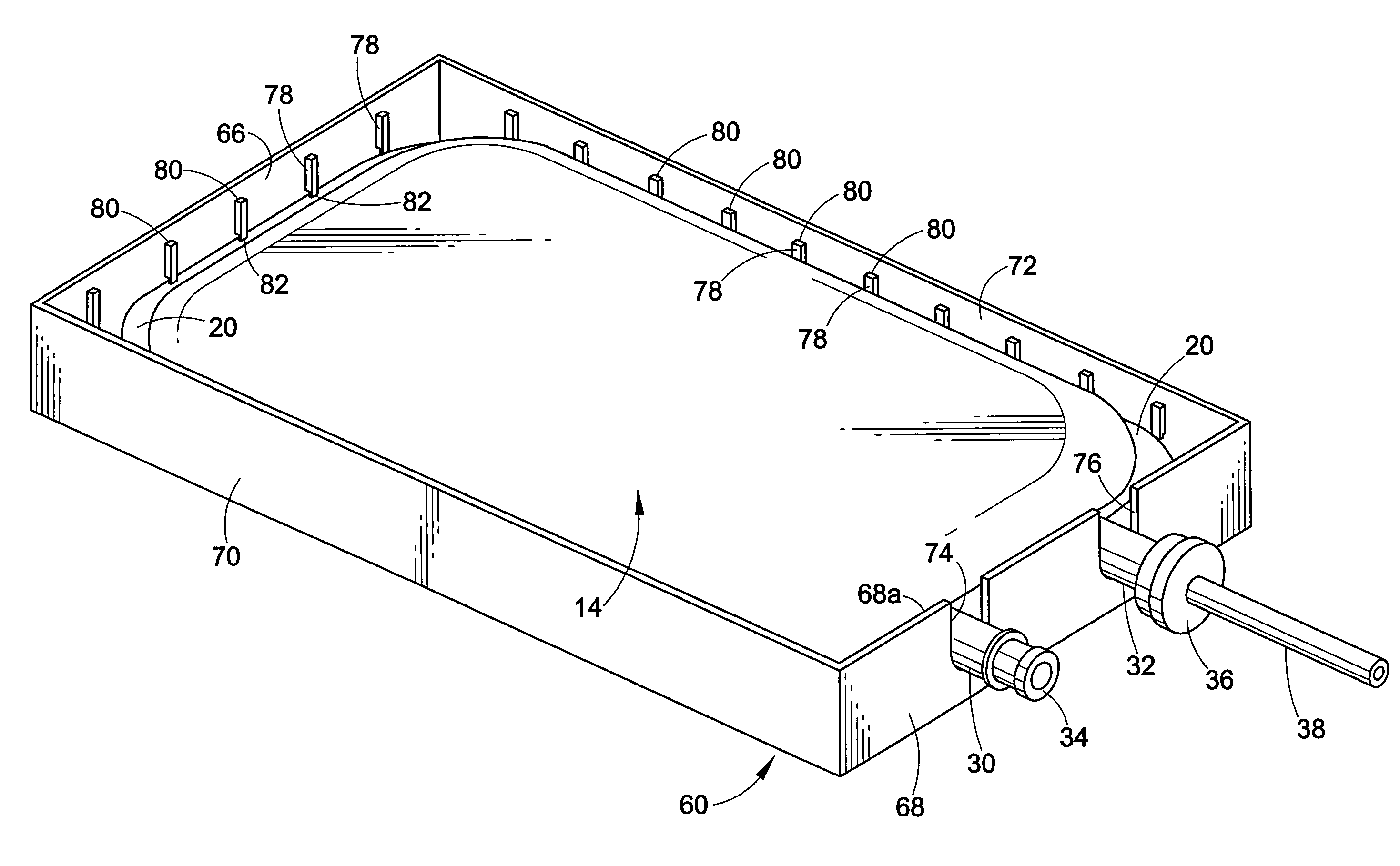
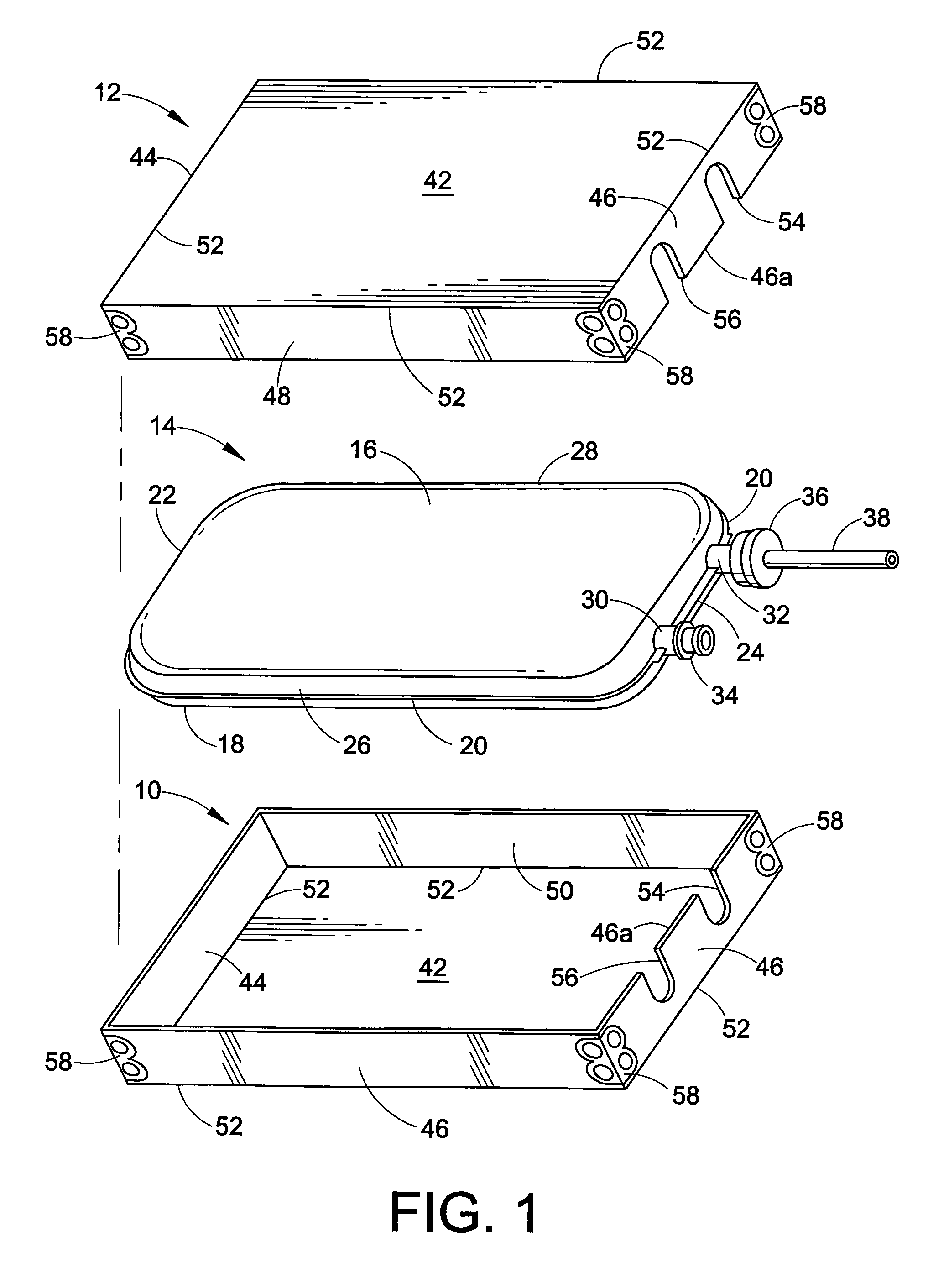
[0017]Referring now in greater detail to the drawings, wherein the showings are for the purpose of illustrating preferred embodiments of the invention only, and not for the purpose of limiting the invention, FIG. 1 illustrates bottom and cover components 10 and 12, respectively, of an enclosure for an ink reservoir bag 14 of an ink delivery system for the continuous refill of disposable ink jet cartridges. Preferably, ink reservoir bag 14 is defined by a pair of sheets of flexible plastic material 16 and 18 bonded together, such as by heat sealing, to provide a peripheral edge 20 therebetween. Bag 14 is rectangular in contour and, in this respect, has longitudinally opposite ends 22 and 24, laterally opposite sides 26 and 28 therebetween and top and bottom sides respectively defined by plastic sheets 16 and 18. When filled with ink, as depicted in FIG. 1, the bag has a height between the top and bottom sides and, preferably, the length, width and height dimensions provide an aspect ...


PUM


Abstract

An enclosure for an ink reservoir bag in an ink delivery system for an ink cartridge comprises a tray and a cover for the tray. The tray includes a bottom wall having opposite ends and opposite sides, end walls extending upwardly from said bottom wall at the opposite ends and side walls extending upwardly from the bottom wall along the opposite sides. One of the end walls of the tray has a pair of openings therethrough between the side walls to receive fill and exit ports of the reservoir bag.

Description

BACKGROUND OF THE INVENTION[0001]This invention relates to the art of ink jet printers and, more particularly, to enclosures for ink reservoir bags for supplying ink to an ink cartridge in a continuous ink supply system.[0002]Continuous ink refill systems for disposable ink jet cartridges are of course well known as shown, for example, in U.S. Pat. Nos. 5,469,201 to Erickson, et al. and 5,745,137 to Scheffelin, et al., both of which are incorporated herein by reference for background information. In such systems, basically, a cartridge is connected to an auxiliary supply reservoir by means of a flexible hose or tube and, during operation of the printing system, the tube is open to allow ink to flow from the reservoir to the ink cartridge. During shipping or handling of the ink supply reservoir / cartridge system, when the latter is outside the print machine, and when the system is installed in a printer, it is important to protect the reservoir bag from the application of excessive pr...

Claims


Application Information

Patent Timeline
IPC IPC(8): B41J2/175
CPCB41J2/17513B41J2/17553
Inventor HOLLAND, CARL W.PUTMAN, WILLIAM A.
Owner NU KOTE INT
Why Eureka
Try Eureka