
Riser rotating control device

a control device and rotating control technology, applied in the direction of survey, sealing/packing, borehole/well accessories, etc., can solve the problems of increasing drilling costs, increasing the amount of known resources considered economically undrillable, and excluding gas hydrates

Active Publication Date: 2009-02-10
WEATHERFORD TECH HLDG LLC
View PDF362 Cites 142 Cited by
  • Summary
  • Abstract
  • Description
  • Claims
  • Application Information

AI Technical Summary

Benefits of technology

This solution enhances operational efficiency by reducing the need for manual intervention in the moon pool, improving safety, and allowing for more efficient pressure management in deepwater drilling operations.

Problems solved by technology

However, a majority of known resources, gas hydrates excluded, are considered economically undrillable with conventional techniques.
Pore pressure depletion, the need to drill in deeper water, and increasing drilling costs indicate that the amount of known resources considered economically undrillable will continue to increase.
However, rig operators typically bolt conventional rotating control devices to a riser below the rotary table of a drilling rig.
Such a fixed connection has presented health, safety, and environmental (HSE) problems for drilling operators because retrieving the rotating control device has required unbolting the rotating control device from the riser, requiring personnel to go below the rotary table of the rig in the moon pool to disconnect the rotating control device.
In addition to the HSE concerns, the retrieval procedure is complex and time consuming, decreasing operational efficiency of the rig.
Furthermore, space in the area above the riser typically limits the drilling rig operator's ability to install equipment on top of the riser.

Method used


Image

  • Riser rotating control device
  • Riser rotating control device
  • Riser rotating control device

Examples


Embodiment Construction

[0034]Although the following is described in terms of a fixed offshore platform environment, other embodiments are contemplated for onshore use. Additionally, although the following is described in terms of oilfield drilling, the disclosed embodiments can be used in other operating environments and for drilling for non-petroleum fluids.

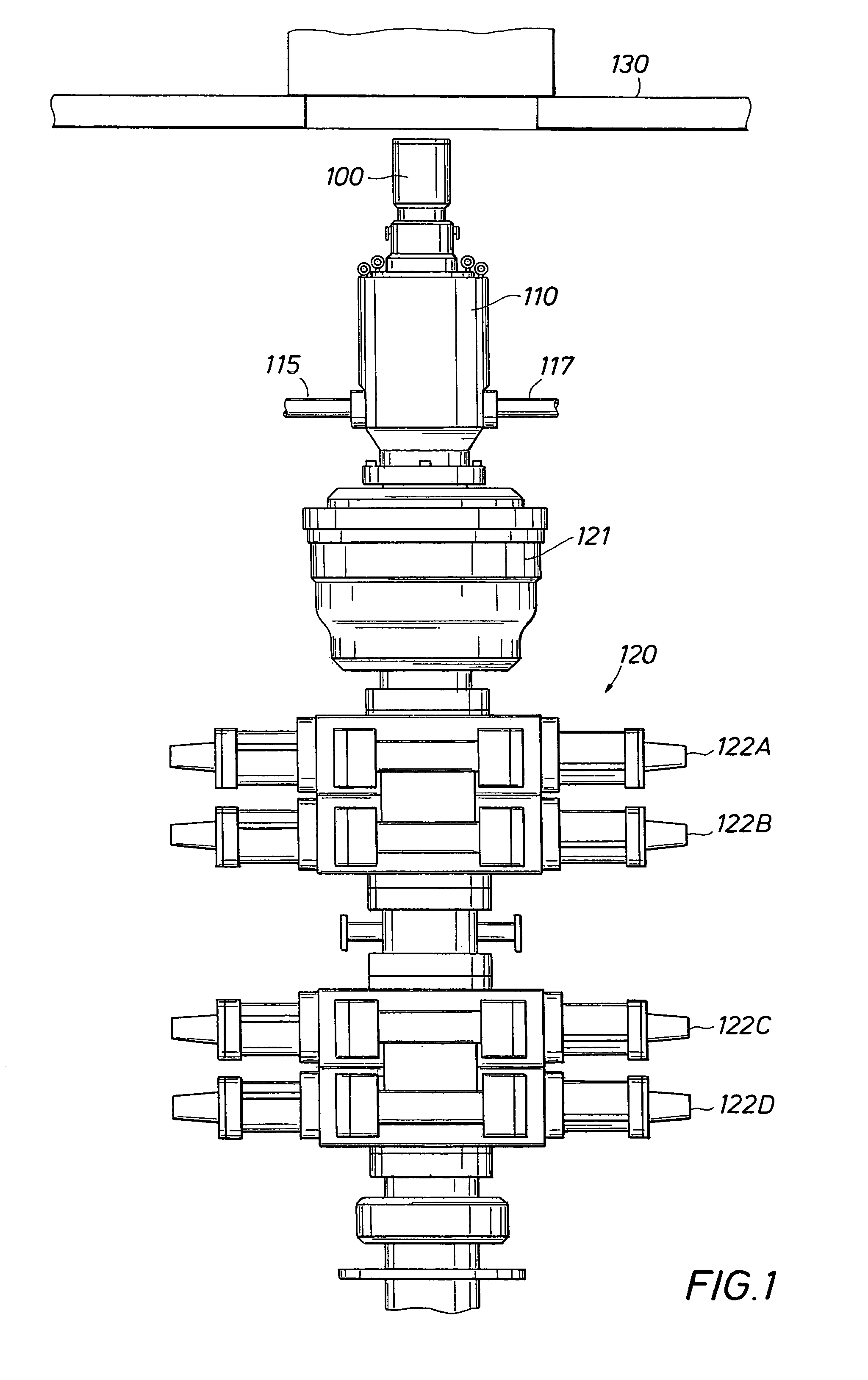
[0035]Turning to FIG. 1, a rotating control device 100 is shown latched into a riser or bell nipple 110 above a typical blowout preventer (BOP) stack, generally indicated at 120. As illustrated in FIG. 1, the exemplary BOP stack 120 contains an annular BOP 121 and four ram-type BOPs 122A-122D. Other BOP stack 120 configurations are contemplated and the configuration of these BOP stacks is determined by the work being performed. The rotating control device 100 is shown below the rotary table 130 in a moon pool of a fixed offshore drilling rig, such as a jackup or platform rig. The remainder of the drilling rig is not shown for clarity of the figure and...


PUM


Abstract

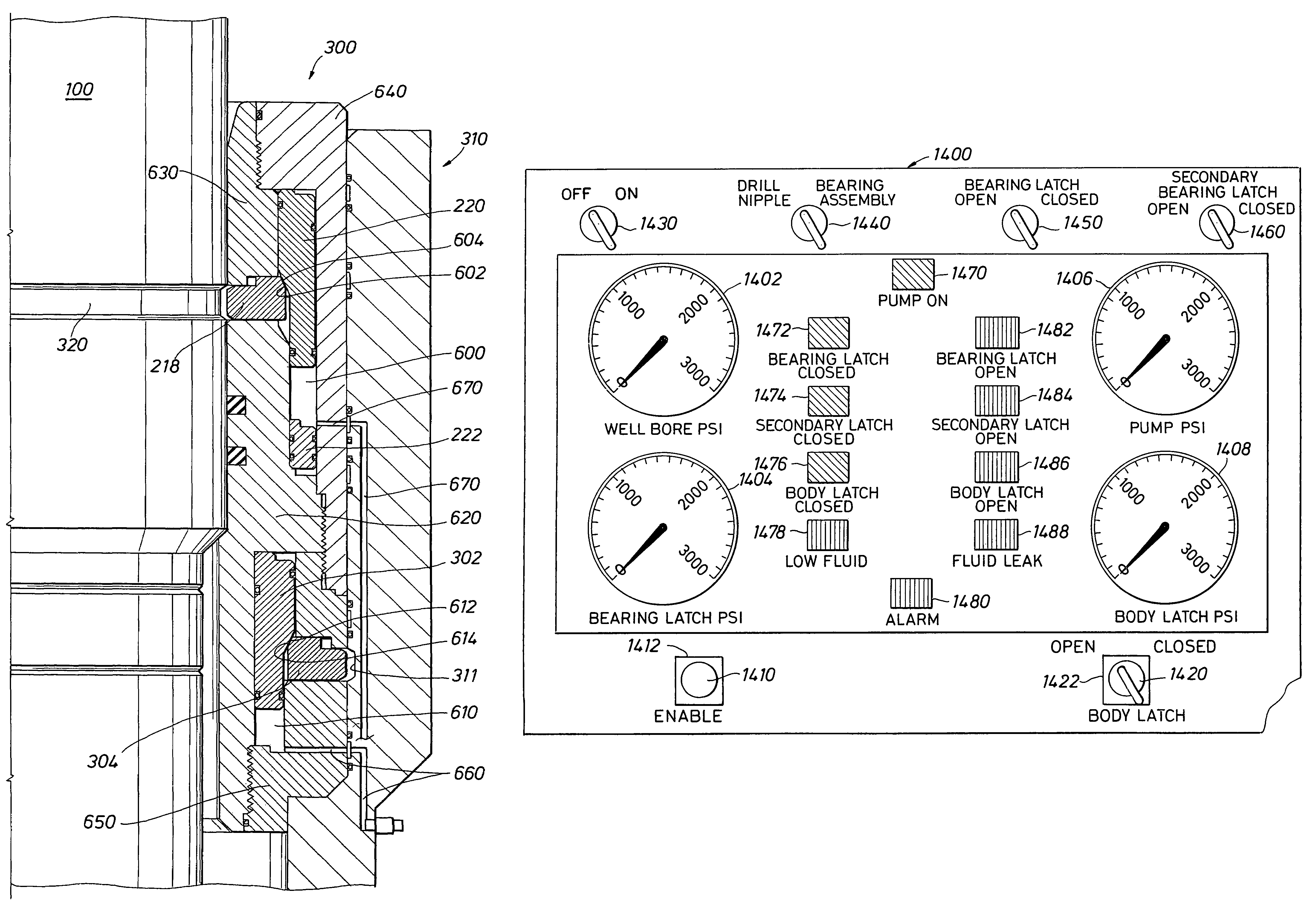
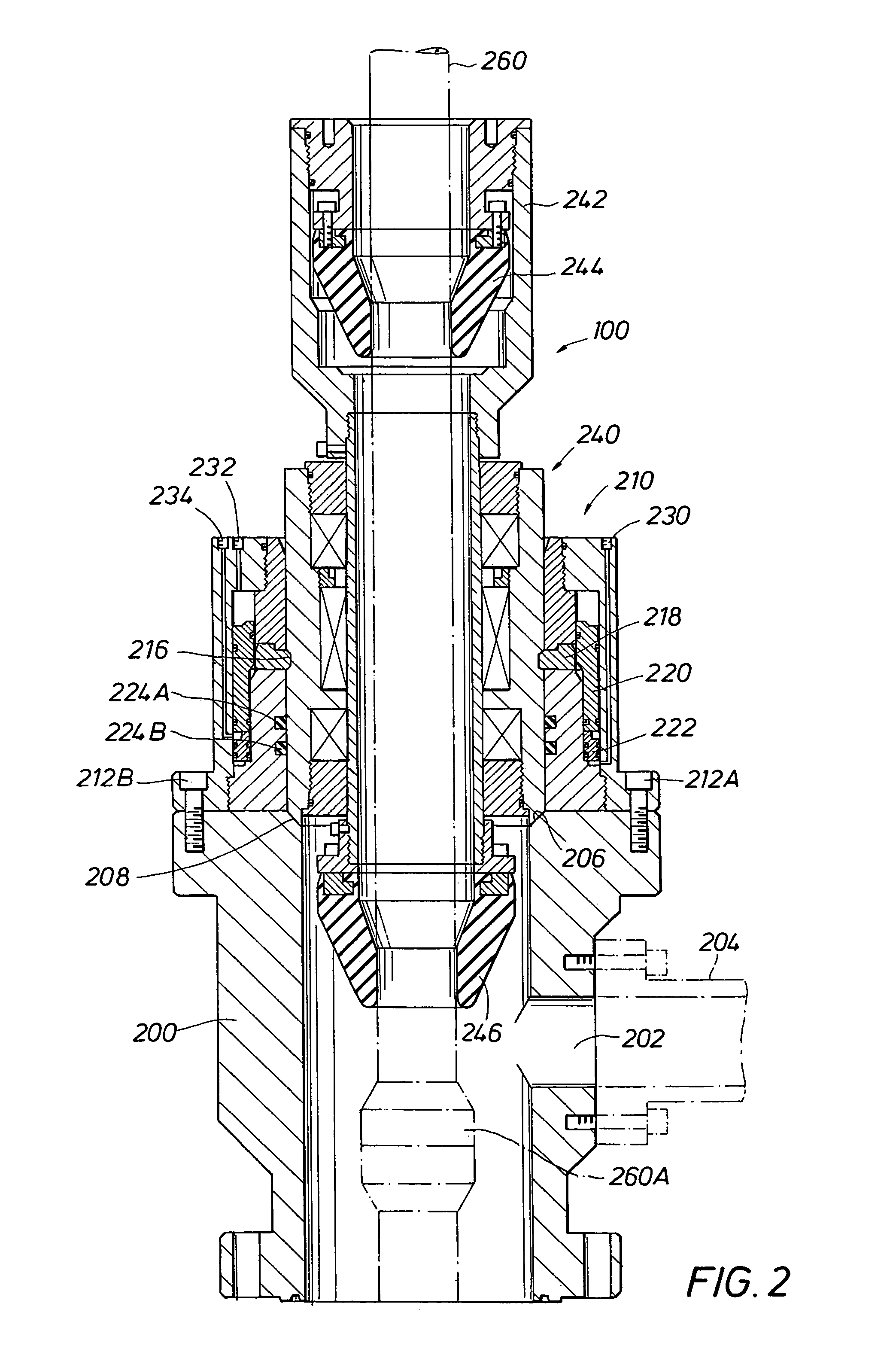
A latch assembly is connectable to a riser. A rotating control device can be positioned with the riser, sealing the rotating control device with the latch assembly and removably latching the rotating control device to the latch assembly and to the riser. The latch assembly can be remotely actuated. The latch assembly can provide an auxiliary safety mechanism to provide a backup actuation mechanism to unlatch the rotating control device from the latch assembly. The latch assembly can be bolted to the riser. Alternately, the latch assembly can be latched with the riser using a similar latching mechanism as used to latch the latch assembly to the rotating control device. A pressure transducer protector assembly can protect a transducer for monitoring wellbore pressure in the riser. A remote indicator panel can indicate the status of the latch assembly.

Description

CROSS-REFERENCE TO RELATED APPLICATIONS[0001]N / ASTATEMENTS REGARDING FEDERALLY SPONSORED RESEARCH OR DEVELOPMENT[0002]N / AREFERENCE TO A MICROFICHE APPENDIX[0003]N / ABACKGROUND OF THE INVENTION[0004]1. Field of the Invention[0005]The present invention relates to the field of oilfield drilling equipment and in particular to an apparatus and method for remotely sealing and latching a rotating control device with a riser.[0006]2. Description of the Related Art[0007]Conventional offshore drilling techniques focus upon a decades-old technique that was hydraulic pressure generated by a preselected fluid inside the wellbore to control pressures in a formation being drilled. However, a majority of known resources, gas hydrates excluded, are considered economically undrillable with conventional techniques.[0008]Pore pressure depletion, the need to drill in deeper water, and increasing drilling costs indicate that the amount of known resources considered economically undrillable will continue t...

Claims


Application Information

Patent Timeline
Patent Type & Authority Patents(United States)
IPC IPC(8): E21B29/12E21BE21B33/08
CPCE21B33/085Y10S285/92E21B33/035
Inventor BAILEY, THOMAS F.CHAMBERS, JAMES W.
Owner WEATHERFORD TECH HLDG LLC
Learn More