
Speech decoder and a method for decoding speech

a speech decoding and speech technology, applied in the field of speech decoding and speech decoding methods, can solve the problems of increasing the time that must be allocated, affecting the quality of speech, and unable to guarantee the full one-to-one compatibility of sampling rates, so as to achieve the effect of widening the bandwidth

Inactive Publication Date: 2009-01-27
NOKIA TECHNOLOGLES OY
View PDF22 Cites 9 Cited by
  • Summary
  • Abstract
  • Description
  • Claims
  • Application Information

AI Technical Summary

Benefits of technology

[0010]It is an object of the present invention to present a speech decoder and a method for decoding speech where the expansion of a frequency band is made in a flexible way which is computationally economical and imitates well the characteristics that would be obtained by originally using a wider bandwidth.
[0024]In order to ensure that the wideband LP filter does not give rise to excessive amplification close to the Nyquist frequency, it is advantageous to place certain limitations to the last element(s) of the wideband LP filter's vector representation. Especially the difference between the last element in the vector representation and the Nyquist frequency, proportioned to the sampling frequency, should stay approximately the same. These limitations are easily defined through differential definitions so that the difference between adjacent elements in the vector representation is controlled.

Problems solved by technology

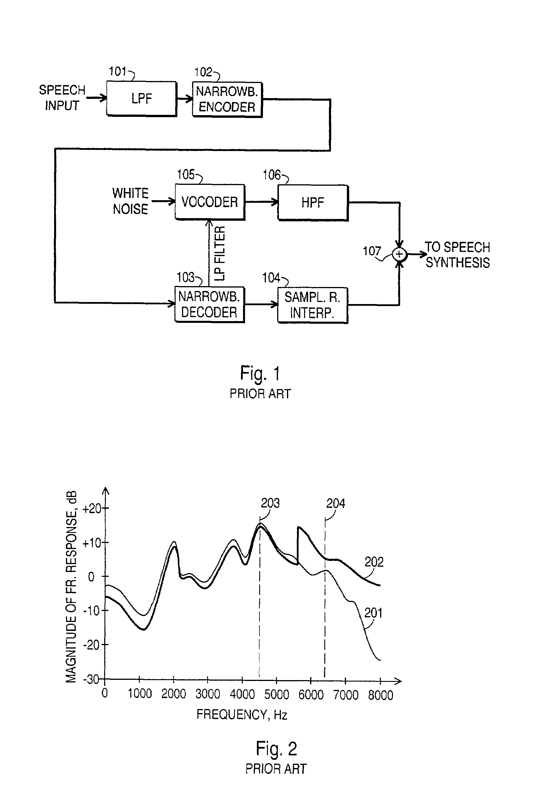
The evolution of second generation digital cellular networks and their functionally enhanced terminals has resulted in a situation where full one-to-one compatibility regarding sampling rates can not be guaranteed, i.e. the speech encoder in the transmitting terminal may use an input sampling rate which is different than the output sampling rate of the speech decoder in the terminal.
The use of a look-up table in searching for the characteristics of a suitable wideband filter may help to avoid disasters of the kind shown in FIG. 2, but simultaneously it involves a considerable degree of inflexibility.
Increasing the number of stored wideband filter configurations to choose from also increases the time that must be allocated for searching for and setting up the right one of them, which is not desirable in real time operation like speech telephony.

Method used


Image

  • Speech decoder and a method for decoding speech
  • Speech decoder and a method for decoding speech
  • Speech decoder and a method for decoding speech

Examples


Embodiment Construction

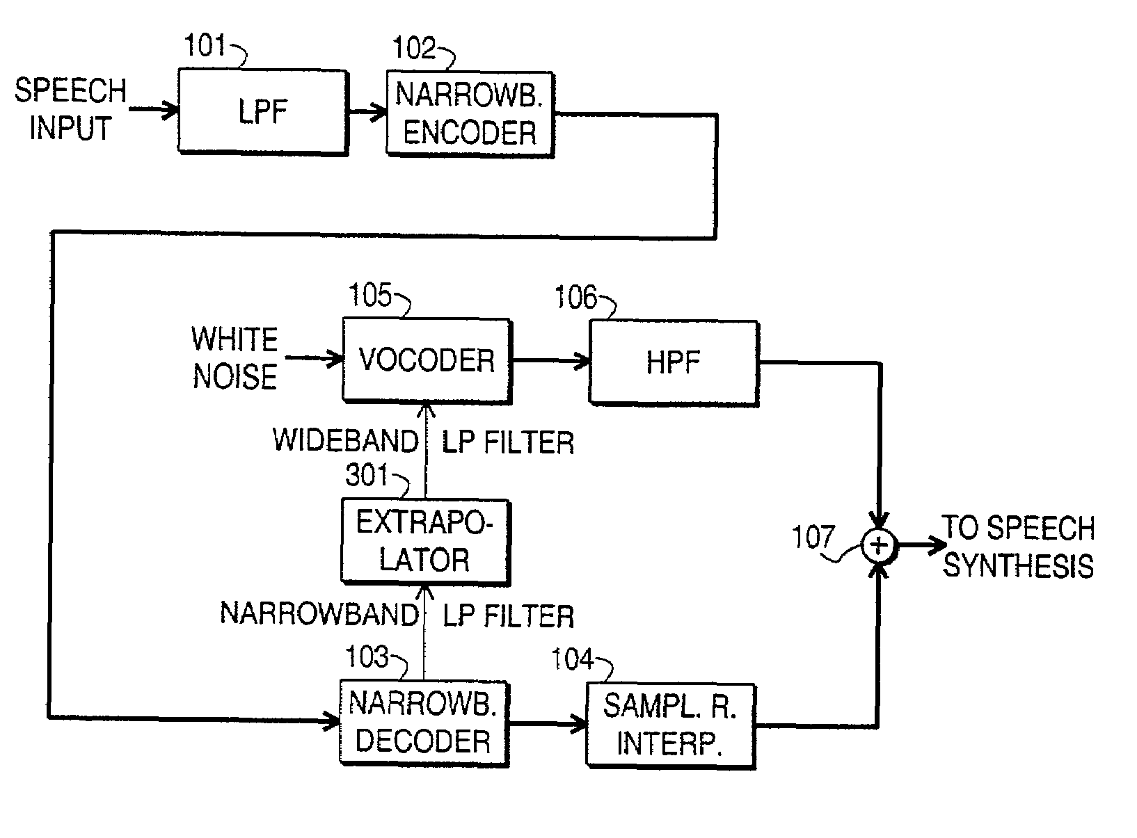
[0035]FIG. 3a illustrates the use of a narrowband input signal to extract the parameters of a narrowband LP filter in an extracting block 310. The narrowband LP filter parameters are taken into an extrapolation block 301 where extrapolation is used to produce the parameters of a corresponding wideband LP filter. These are taken into a vocoder 105 which uses some wideband signal as its input. The vocoder 105 generates a wideband LP filter from the parameters and uses them to convert the wideband input signal into a wideband output signal. Also the extracting block 310 may give an output, which is a narrowband output.

[0036]FIG. 3b shows how the principle of FIG. 3a can be applied to an otherwise known speech decoder. A comparison between FIG. 1 and FIG. 3b shows the addition brought through the invention into the otherwise known principle for converting a narrowband encoded speech signal into a wideband decoded sample stream. The invention does not have an effect on the transmitting e...


PUM


Abstract

A speech decoder comprises a decoder (103) for converting a linear prediction encoded speech signal into a first sample stream having a first sampling rate and representing a first frequency band. Additionally it comprises a vocoder (105) for converting an input signal into a second sample stream having a second sampling rate and representing a second frequency band, and combination means (107) for combining the first and second sample streams in processed form. It comprises also means (301) for generating a second linear prediction filter, to be used by the vocoder (105) on the second frequency band, on the basis of a first linear prediction filter used by the decoder (103) on the first frequency band. Extrapolation through an infinite impulse response filter is the preferable method of generating the second linear prediction filter.

Description

TECHNOLOGICAL FIELD[0001]The invention concerns in general the technology of decoding digitally encoded speech. Especially the invention concerns the technology of generating a wide frequency band decoded output signal from a narrow frequency band encoded input signal.BACKGROUND OF THE INVENTION[0002]Digital telephone systems have traditionally relied on standardized speech encoding and decoding procedures with fixed sampling rates in order to ensure compatibility between arbitrarily selected transmitter-receiver pairs. The evolution of second generation digital cellular networks and their functionally enhanced terminals has resulted in a situation where full one-to-one compatibility regarding sampling rates can not be guaranteed, i.e. the speech encoder in the transmitting terminal may use an input sampling rate which is different than the output sampling rate of the speech decoder in the terminal. Also the linear prediction or LP analysis of the original speech signal may be perfo...

Claims


Application Information

Patent Timeline
Patent Type & Authority Patents(United States)
IPC IPC(8): G10L19/04G10L13/00G10L19/02G10L19/16H03M7/36
CPCG10L19/16G10L19/0212G10L19/04G10L19/02
Inventor ROTOLA-PUKKILA, JANIVAINIO, JANNEMIKKOLA, HANNU
Owner NOKIA TECHNOLOGLES OY
Learn More