
Automatic compositing of 3D objects in a still frame or series of frames

a 3d object and still frame technology, applied in the field of image rendering, can solve the problems of inability to accurately render the effect of the 2d environment on the 3d object, time-consuming and thus expensive job, etc., and achieve the effect of effective rendering

Active Publication Date: 2009-01-13
KOTAB DOMINIC M
View PDF25 Cites 36 Cited by
  • Summary
  • Abstract
  • Description
  • Claims
  • Application Information

AI Technical Summary

Benefits of technology

"The patent describes a system and method for creating photo-realistic renderings of 3D objects added to a still frame or series of frames. The system analyzes the 2D image frame, adds the 3D objects, and applies visual effects with little user intervention. The effects can include shadowing, reflection, refraction, and transparency. The system can also detect and match shadows in the frame with the added 3D objects, and render the objects in a way that takes into account their shape and depth. The system can also adjust the visual effects to reflect the refraction caused by the transparent or semi-transparent portions of the 3D objects. The invention can be implemented in hardware, software, or a combination of both."

Problems solved by technology

However, where the environment does not have Z data associated with it, and is thus by definition a 2D environment, effects of the 2D environment on 3D objects such as reflection, refraction, shadows, etc. have heretofore not been readily and accurately rendered.
However, this system too fails to allow accurate rendering of environmental effects on a 3D object.
This is a very time consuming and thus expensive job, considering that a typical movie runs at about 30 frames per second.
Shadowing is currently performed by dimming the image, which is not an accurate representation of a shadow.
One problem is that the reflections do not look realistic, particularly on rounded or angled surfaces.
Heretofore methods have not been able to accurately create the natural deformation of the reflection due to curvature of the reflecting surface.
Particularly, human artists find it very difficult to conceptualize this deformation and create it in the reflection in the composite image.
Current methods do not account for refractive distortion.

Method used


Image

  • Automatic compositing of 3D objects in a still frame or series of frames
  • Automatic compositing of 3D objects in a still frame or series of frames
  • Automatic compositing of 3D objects in a still frame or series of frames

Examples


Embodiment Construction

[0039]The following description is the best embodiment presently contemplated for carrying out the present invention. This description is made for the purpose of illustrating the general principles of the present invention and is not meant to limit the inventive concepts claimed herein. Further, particular features described herein can be used in combination with other described features in each of the various possible combinations and permutations.

[0040]The following specification describes systems, methods, and computer program products that provide broadcast-quality photo-realistic rendering of one or more 3D objects added to a still frame (photo mode), or series of frames (movie mode). Effects such as reflection, shadows, transparency, and refraction on or of the 3D object(s) relative to objects in the frame are automatically determined and added to the composite image. The software also dynamically determines what object in the frame should be in front of or behind the 3D objec...


PUM


Abstract

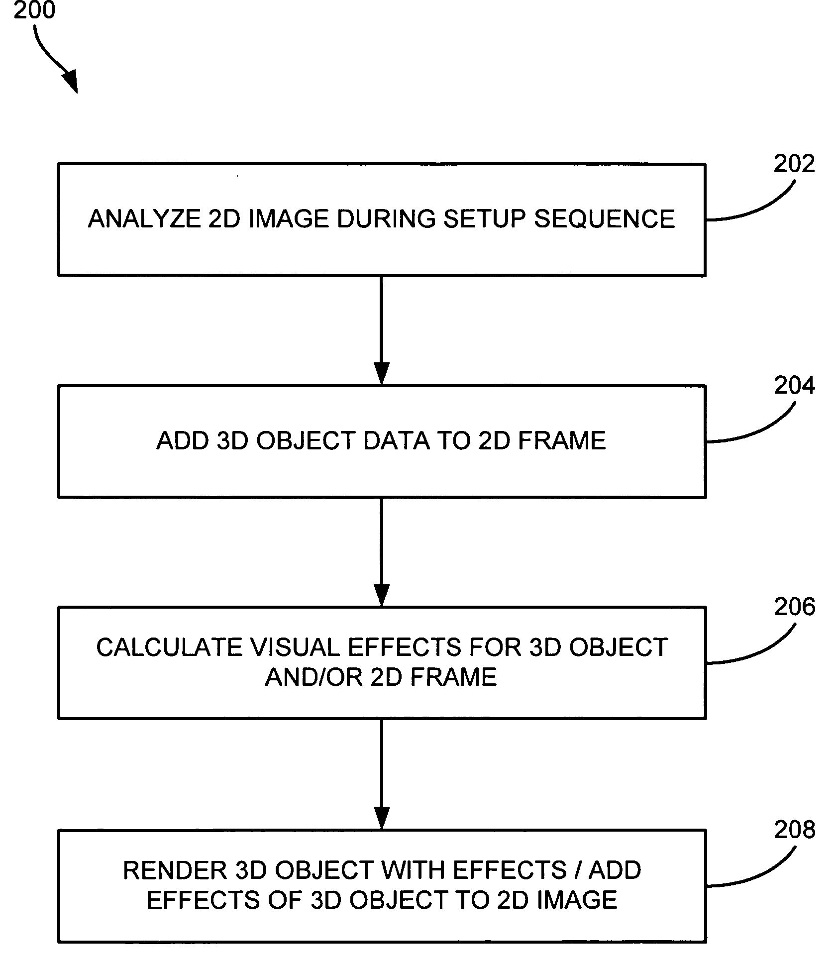
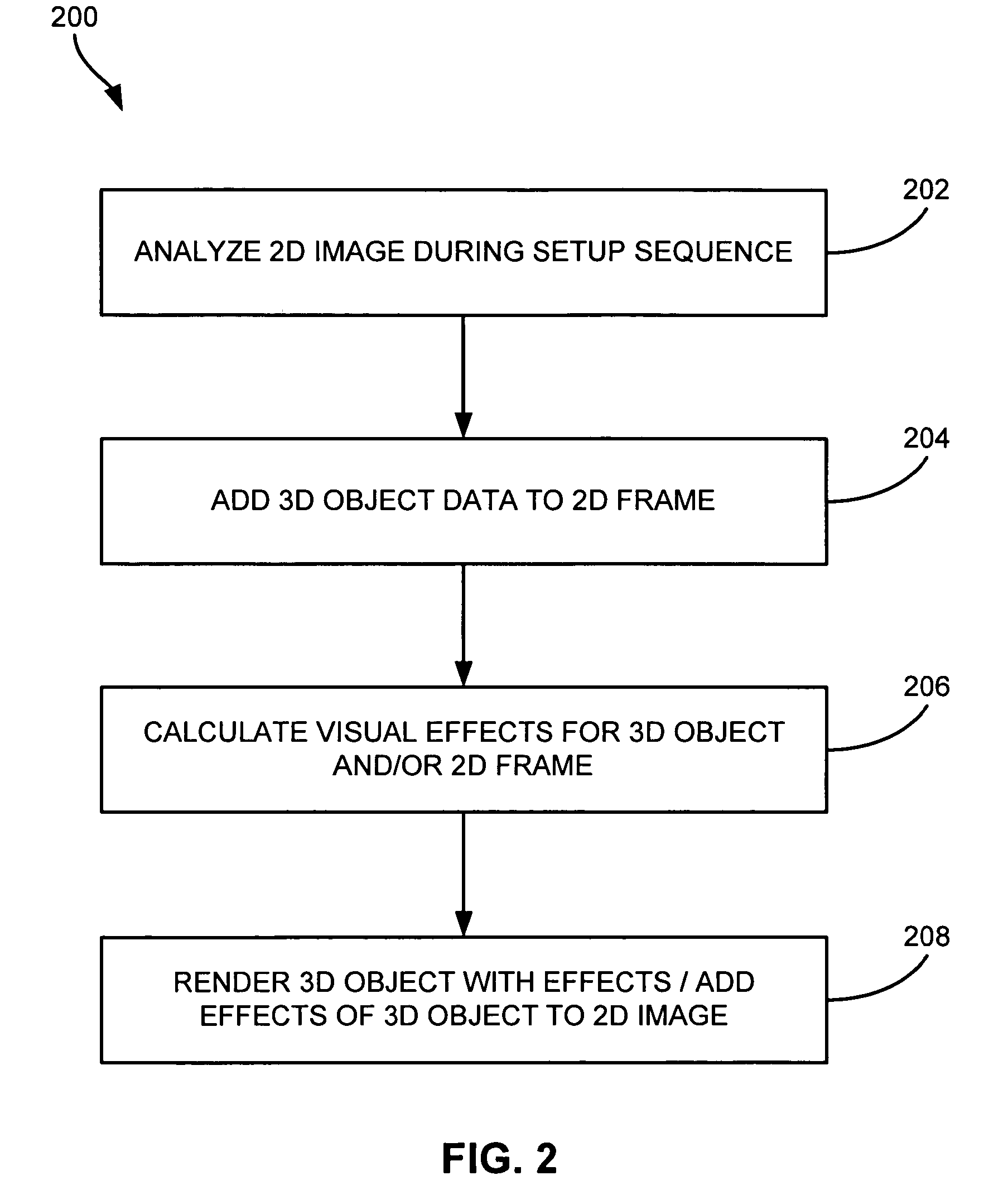
Systems, methods, and computer program products that provide broadcast-quality photo-realistic rendering of one or more 3D objects added to a still frame (photo mode), or series of frames (movie mode). The basic steps performed during creation of an image include analysis of a 2D image frame during a set up sequence, adding a 3D object to the frame, and adding visual effects to the frame with little or no user intervention, the visual effects including but not limited to shadowing, reflection, refraction, and transparency.

Description

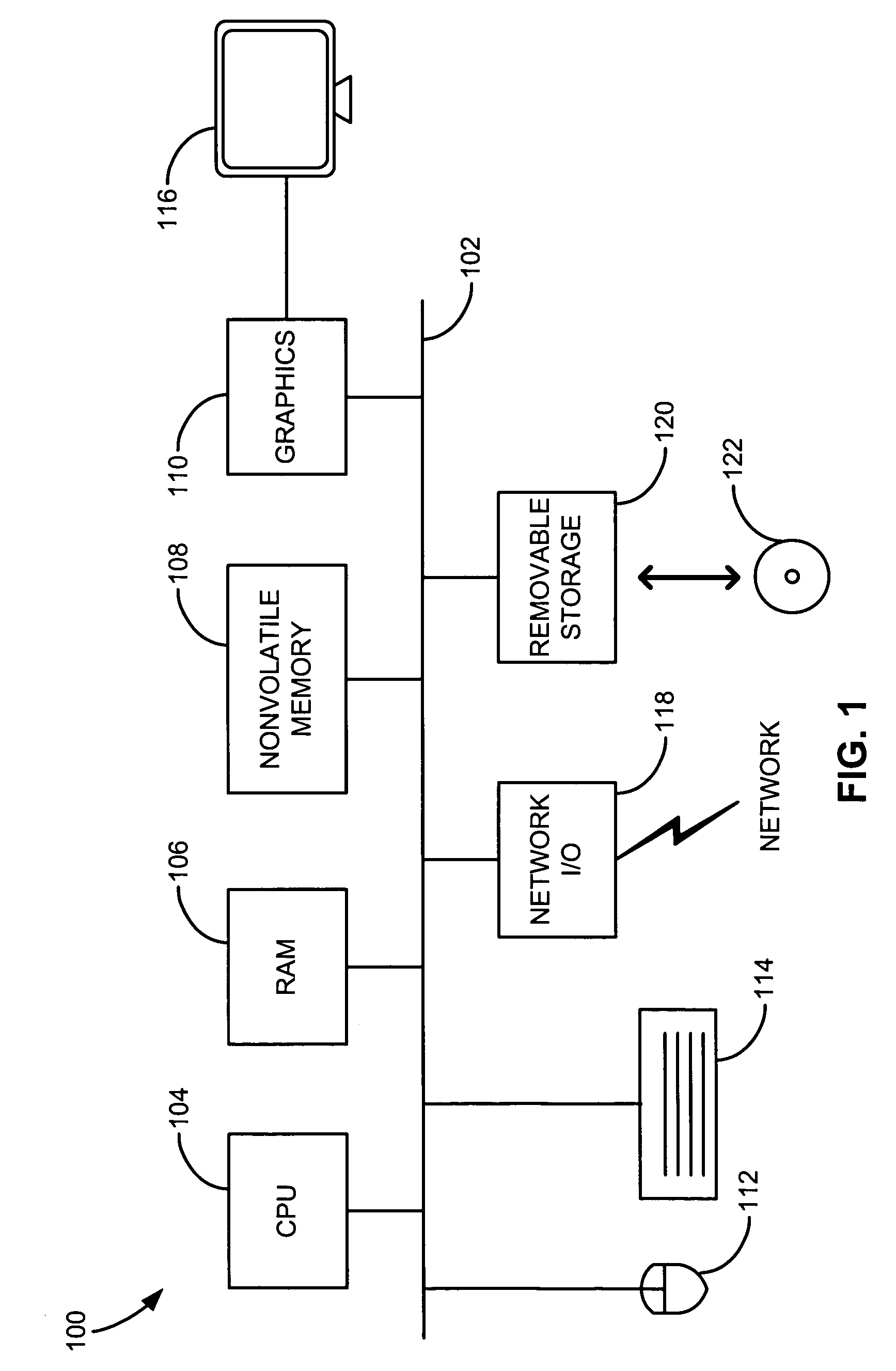
FIELD OF THE INVENTION[0001]The present invention relates to image rendering, and more particularly, this invention relates to automated, accurate compositing of three dimensional (3D) objects added to a two dimensional (2D) frame or series of 2D frames.BACKGROUND OF THE INVENTION[0002]Photography and moviemaking have become staples in modern society. A photograph is typically a single image frame of a real scene. Movies can be described as a series of frames that together form what appears to the human eye to be a continuously moving image. Both photographs and movies are now found in both physical and digital formats.[0003]In recent years, advances in technology have allowed creation of entirely three dimensional worlds. 3D graphic systems are able to produce an image on a two-dimensional screen of a display in such a manner that the image simulates three-dimensional effects. In such 3D systems, the surface of a 3D object to be represented is separated into a plurality of polygona...

Claims


Application Information

Patent Timeline
Patent Type & Authority Patents(United States)
IPC IPC(8): G06K9/00G06T15/00G09G5/00G06T15/50
CPCG06T7/0081G06T11/00G06T15/50G06T15/60G06T7/11
Inventor WELLS, BARTON S.
Owner KOTAB DOMINIC M
Learn More