
Label applicator

a label applicator and label technology, applied in the field of automatic bench tools, can solve the problems of unfinished end products, skin oil and dirt contamination of labels, and burdened the efficiency of such applicators, and achieve the effect of minimal flagging

Active Publication Date: 2008-12-30
HELLERMANNTYTON CORP
View PDF25 Cites 20 Cited by
  • Summary
  • Abstract
  • Description
  • Claims
  • Application Information

AI Technical Summary

Benefits of technology

[0011]The preferred labels to be used in accordance with the present invention are preferably continuous sheets of a suitable label material carried on continuous sheets of releasable liner material. The labels may be preprinted and supplied in a spindled roll, or may be printed at need by an optionally attached printing system, thus allowing labels to be easily kitted for each label job. Further, the labels may preferably include datum marks printed on the liner material.

Problems solved by technology

Further, several problems have burdened the efficiency of such applicators.
This results in skin oil and dirt contamination of labels.
Label contamination also may cause flagging and an end product having an unfinished appearance.
Additionally manufacturers using prior art applicators typically allocate more than fifteen seconds to manually apply one standard label.

Method used


Image

  • Label applicator
  • Label applicator
  • Label applicator

Examples


Embodiment Construction

[0044]Although the disclosure hereof is detailed and exact to enable those skilled in the art to practice the invention, the physical embodiments herein disclosed merely exemplify the invention, which may be embodied in other specific structure. While the preferred embodiment has been described, the details may be changed without departing from the invention, which is defined by the claims.

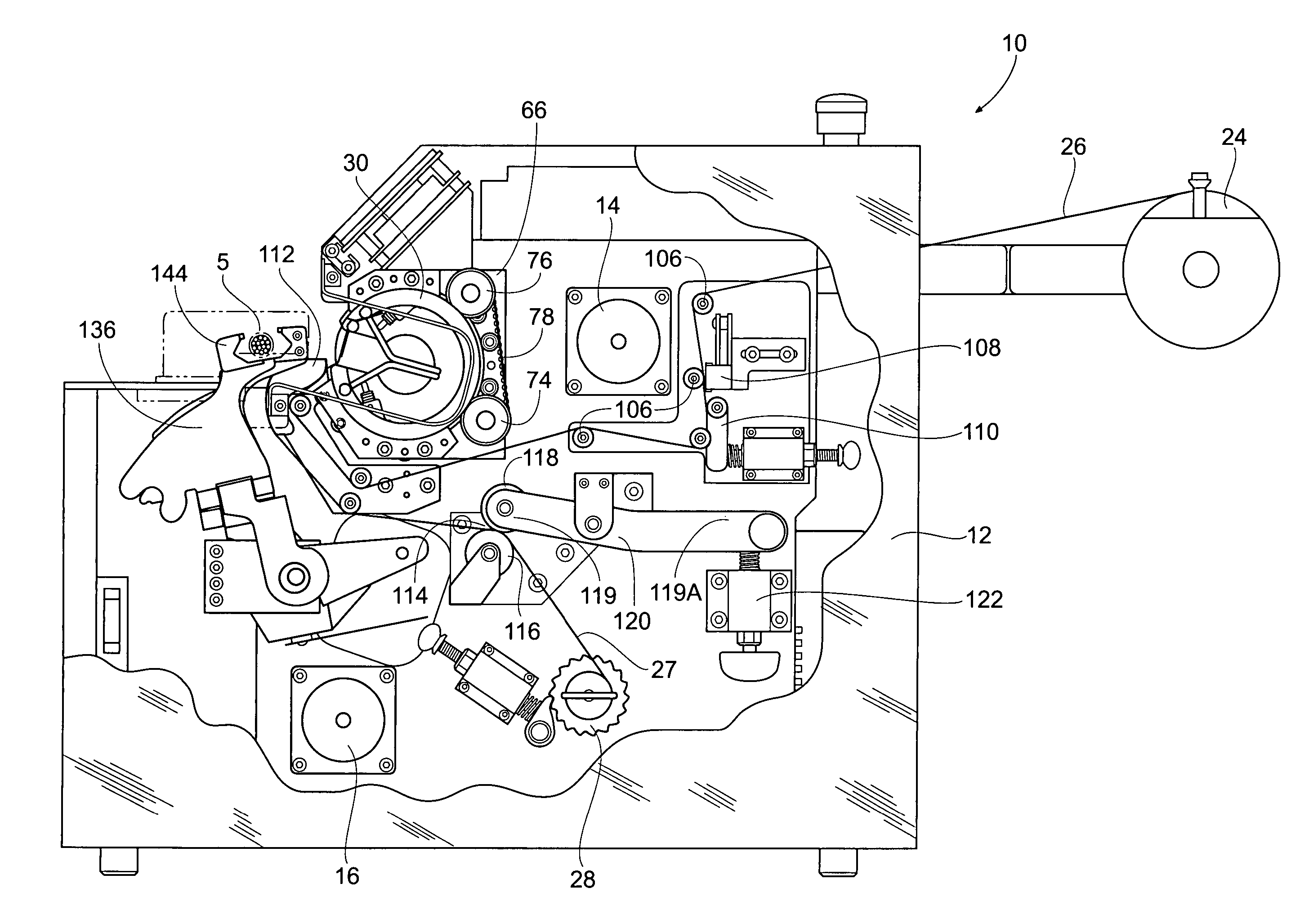
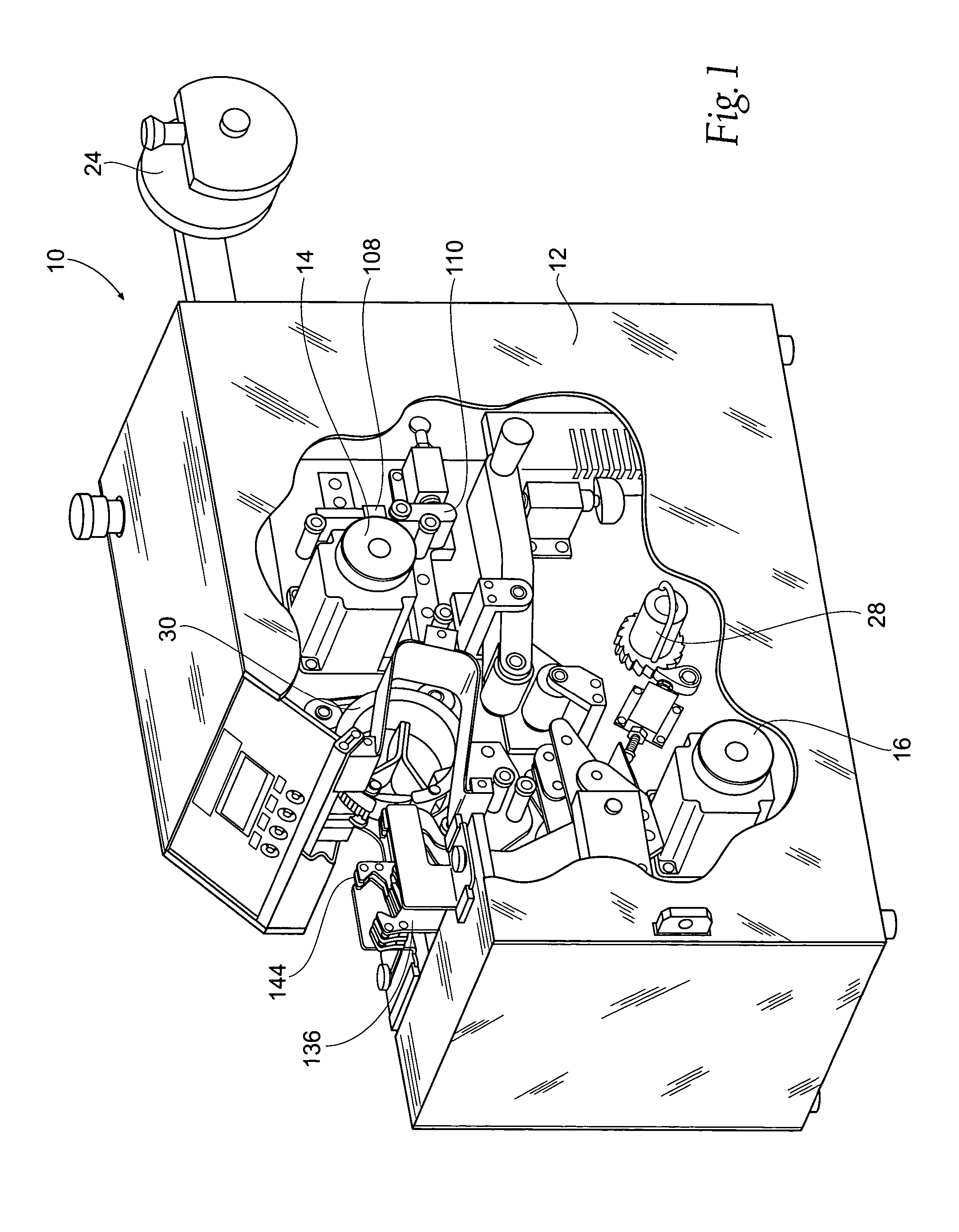
[0045]Turning now to the drawings, in which like reference numerals refer to corresponding elements throughout the views, attention is first directed to FIG. 1 illustrating a perspective view of the apparatus 10 with a portion of the side panel 12 broken away so that the various components of the apparatus 10 may be seen.

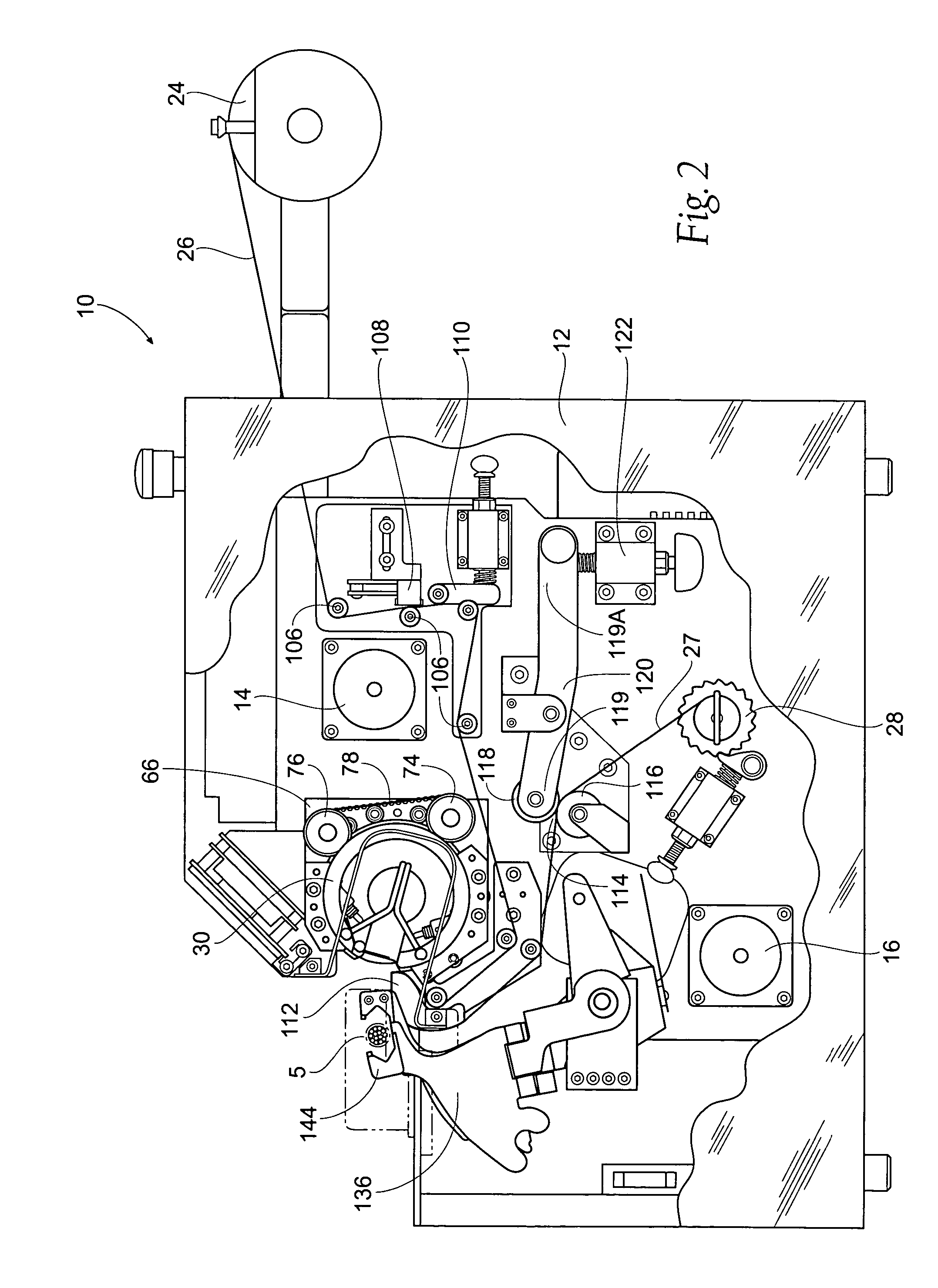
[0046]The label assembly 10 preferably includes two independently operated motors, the first of which will be identified herein as a drive motor 14, the second of which will be identified as a gripper arm motor 16. As may be seen particularly in FIGS. 3 and 4, the drive motor 14 i...


PUM

PropertyMeasurementUnit
obtuse angleaaaaaaaaaa
pressureaaaaaaaaaa
timeaaaaaaaaaa

Abstract

An apparatus and method for wrapping adhesive backed labels around elongate articles, such as electrical wires including a rotatable puck assembly having an interrupted circumferential surface defining an opening for receiving an elongate object to be labeled and wing members for applying the label during rotation.

Description

RELATED APPLICATIONS[0001]This application claims the benefit of co-pending provisional patent application Ser. No. 60 / 464,508, filed 22 Apr. 2003.BACKGROUND OF THE INVENTION[0002]This invention relates to an automatic bench tool for automatic application of labels to wires, cables, or other elongate articles.[0003]In the past, labels have been applied to elongate articles such as wires and cables by way of applicators requiring cumbersome, noisy hydraulic or high-pressure air lines. Further, several problems have burdened the efficiency of such applicators. For example, previous label applicators have required the operator to manually handle the labels during application. This results in skin oil and dirt contamination of labels. Label contamination also may cause flagging and an end product having an unfinished appearance. The present applicator requires no such manual handling and therefore produces a clean, finished product. Additionally manufacturers using prior art applicators...

Claims


Application Information

Patent Timeline
Patent Type & Authority Patents(United States)
IPC IPC(8): B32B15/00B65C3/02
CPCB65C3/02Y10T156/1707
Inventor FRIES, TODDLUESCHEN, WILLIAM K.
Owner HELLERMANNTYTON CORP
Learn More