
Closure and dispensing device

a technology for dispensing devices and containers, which is applied in the direction of liquid dispensing, containers, closure lids, etc., can solve the problems of difficult or impossible to correctly adjust the inclination imparted, difficult or impossible manipulation of containers fitted with caps according to fr 1,161,611, and only obtained the open position. , to achieve the effect of facilitating passage and increasing the length of the lid

Inactive Publication Date: 2008-12-23
LOREAL SA
View PDF12 Cites 1 Cited by
  • Summary
  • Abstract
  • Description
  • Claims
  • Application Information

AI Technical Summary

Benefits of technology

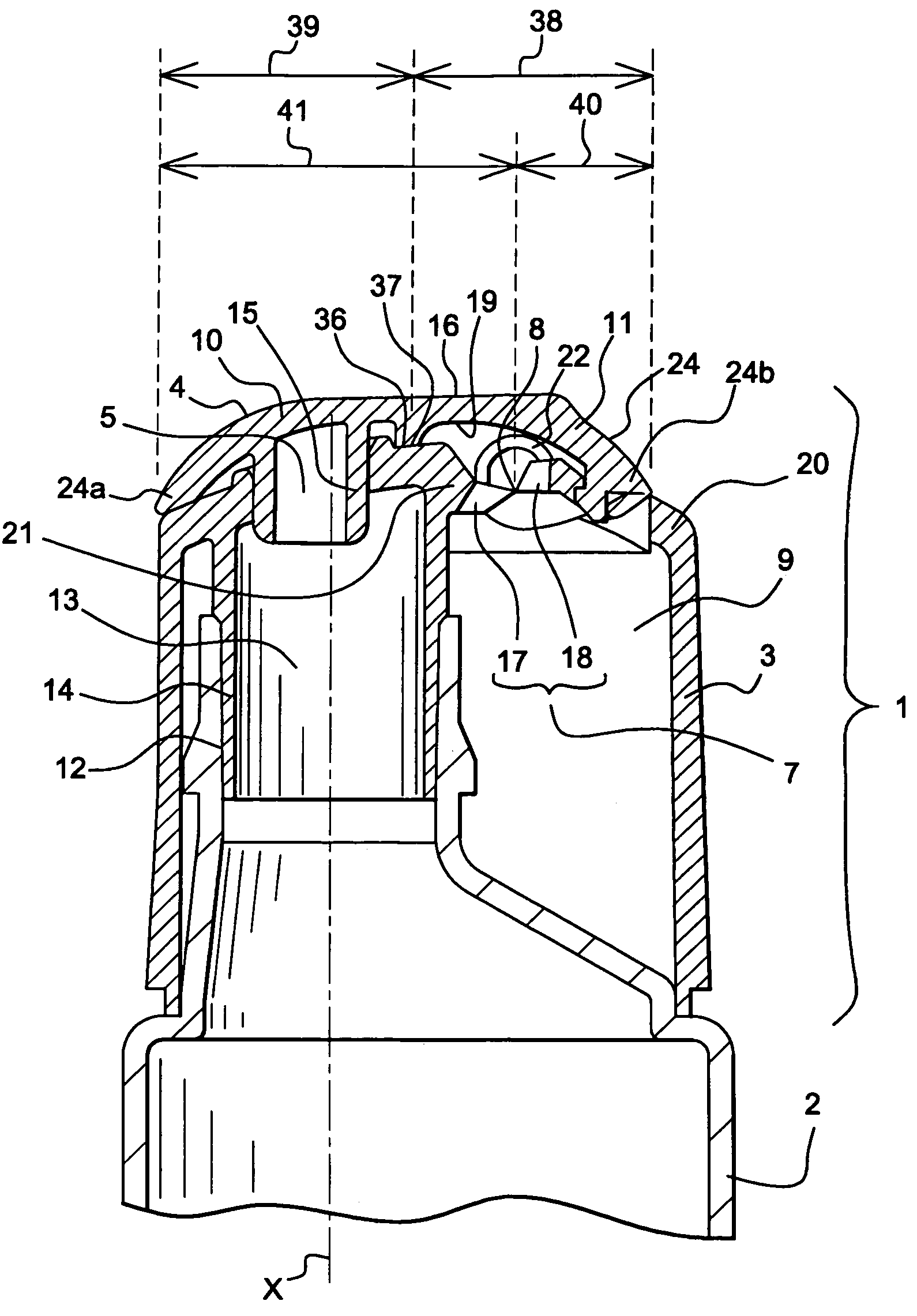
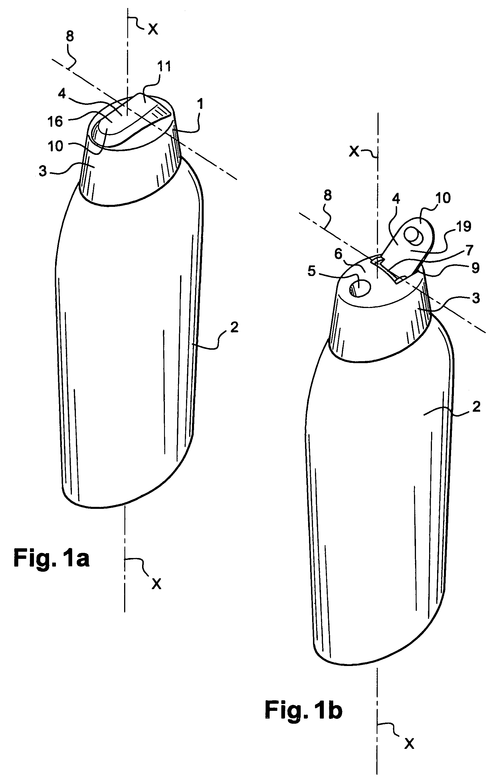
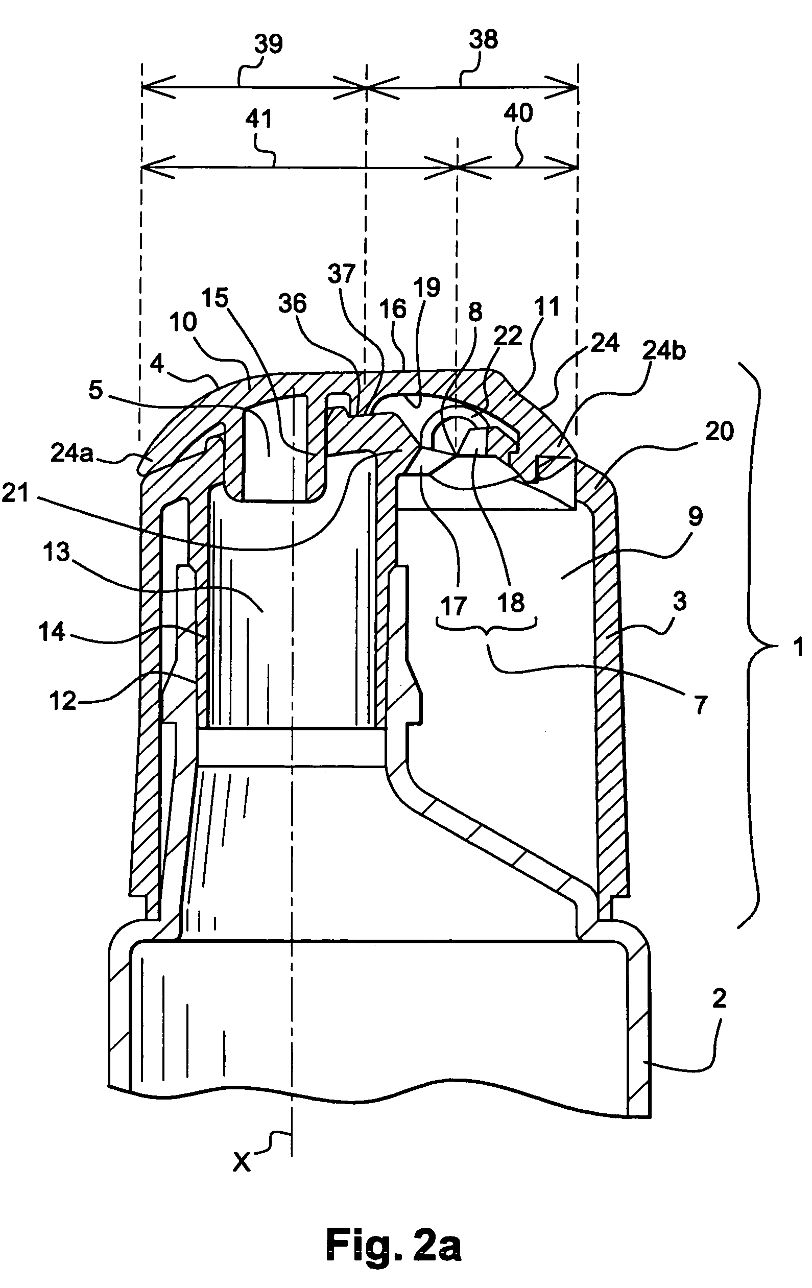
[0013]According to one aspect of the invention, a container having a dispensing cap is provided. In a closed position, this type of cap serves to close off an opening in the container on which it is mounted. In an open position the cap facilitates dispensing of the product held in the container via a dispensing aperture that is in fluid communication with the contents of the container. A spring-effect hinge serves to ease the passage from the closed position to the open position.
[0041]Preferably, pressure exerted on an outer surface of the locking arrangement, in at least one direction parallel to the bearing surface, facilitates compression of the resilient tab, and thus enables the movement from the closed position to the open position.

Problems solved by technology

In the embodiment taught by FR 1,161,611, the lid is capable of reverting resiliently to the closed position, but it presents a major drawback in that the open position is only obtained as long as pressure is being exerted on the protuberant part.
A container fitted with a cap according to FR 1,161,611 is not easy to manipulate.
Moreover, with the hand grasping the container it is difficult or impossible to correctly adjust the inclination imparted to the container to a desired position given the complex position which it is compelled to assume.
Dispensing caps known in the prior art pose a number of problems.
And those dispensing caps which can be opened and held with one hand pose problems in that opening can require pressure to be maintained on part of the lid.

Method used


Image

  • Closure and dispensing device
  • Closure and dispensing device
  • Closure and dispensing device

Examples


first embodiment

[0076] by way of example, the locking arrangement 28 can additionally perform this closed position locking function. In this case, the locking arrangement 28 includes at least one resilient tab 32 which bears against the second end 24b of the lid 4 so as to push back the locking arrangement 28 some distance from this second end 24b. The resilient tab 32 extends across the recess formed by the clamp, and notably the recess formed between the upper part 29 and the lower part 30.

[0077]Even though the resilient tab 32 repels the locking arrangement 28, the latter nonetheless remains integral with or coupled to the lid 4, and its travel in this direction is limited by the cooperation between the counterpart projection 31 and the lower part 30. Preferably, the tab 32 is arranged so that when the arrangement 28 mounted on the lid 4 forms an extension 33 of the second end 24b of the lid 4, this extension 33 is then opposite the rim 20 of the cavity 9. In this at-rest position, the arrangeme...

second embodiment

[0078]In a second embodiment, illustrated in FIGS. 7a to 7d, the device 1 does not have a separate locking arrangement as 28. In particular, as shown in FIGS. 7a to 7d, the device 1 includes a resilient tab 50 connected to a cutout part or sloped portion 51 formed in the second portion 11 of the lid 4. Preferably, with this example, the lid 4 and the resilient tab 50 are made in one piece, in particular by molding.

[0079]FIG. 7a shows the position in which the lid 4, the body 3 and the resilient tab 50 can be molded in a single pass. In this molding position, provision is also made to form the second film-hinge 25 between the second end 24b of the lid 4 and the second part 18. This film-hinge 25 extends over part of the circumference of the lid 4. Preferably the film hinge does not extend at the level of or in the portion of the circumference delineated by the cutout 51. The absence of the film-hinge 25 at the cutout 51 makes it easier to move the resilient tab 50 from its molding po...


PUM


Abstract

A closure and dispensing device intended to be fitted to a container. The device includes a body which can be mounted on the container, with the body including a dispensing aperture in communication with an opening by the container. A lid is stable in the open position, and capable of selectively closing off the dispensing aperture, with the lid being pivotable relative to the body about an axis of a hinge. At least one resiliently deformable strip connects the lid to the body, and the lid includes two ends on an axis perpendicular to the hinge axis. The hinge axis is preferably located relative to the ends so that opening of the lid can occur as a result of pressure exerted on a portion of the lid situated between the hinge axis and the opposite end of the lid. The opposite end of the lid preferably includes a portion which at least partially closes off the dispensing aperture.

Description

CROSS REFERENCE TO RELATED APPLICATIONS[0001]This document claims priority to French Application Number 03 50581, filed Sep. 22, 2003 and U.S. Provisional Application No. 60 / 506,728, filed Sep. 30, 2003, the entire contents of which are hereby incorporated by reference.FIELD OF THE INVENTION[0002]The invention relates to closure and / or dispensing devices. More particularly the invention relates to containers fitted with a dispensing cap. Preferably the dispensing cap includes a spring-effect hinge.BACKGROUND OF THE INVENTIONDiscussion of Background[0003]Dispensing caps are extensively described in the prior art, and generally include a body capable of being mounted around a neck delineating an opening in the container. The cap further includes a lid connected to the body by means of a hinge. The body includes a dispensing aperture which is closed off by the lid when the cap is in the closed position. In the open position, the lid at least partially exposes the dispensing aperture to...

Claims


Application Information

Patent Timeline
Patent Type & Authority Patents(United States)
IPC IPC(8): B65D5/72B65D47/08B65D50/04
CPCB65D47/08B65D47/0814B65D50/045
Inventor DELAGE, JEAN-FRANCOIS
Owner LOREAL SA
Learn More