
Cooling arrangement for server blades

a cooling arrangement and server blade technology, applied in the field of housing arrangement, can solve the problems of affecting the installation and expansion possibilities, and achieve the effects of improving accessibility, simplifying and overcoming, and facilitating maintenance and assembly possibilities

Active Publication Date: 2008-12-16
RITTALWERK RUDOLF LOH GMBH & CO KG
View PDF22 Cites 45 Cited by
  • Summary
  • Abstract
  • Description
  • Claims
  • Application Information

AI Technical Summary

Benefits of technology

This configuration simplifies maintenance and expansion by providing easy access to the distributor and connecting lines, reduces the risk of leakage, and facilitates effective cooling and space utilization in blade servers.

Problems solved by technology

Here, a confused and hard to access conduct of the lines results from the conduct of the feed and return lines to the cooling arrangement, and of the connecting line to the distributor, as well as from the installed arrangement of the distributor and the electrical units, which greatly hinders the installation and expansion possibilities.

Method used


Image

  • Cooling arrangement for server blades
  • Cooling arrangement for server blades
  • Cooling arrangement for server blades

Examples


Embodiment Construction

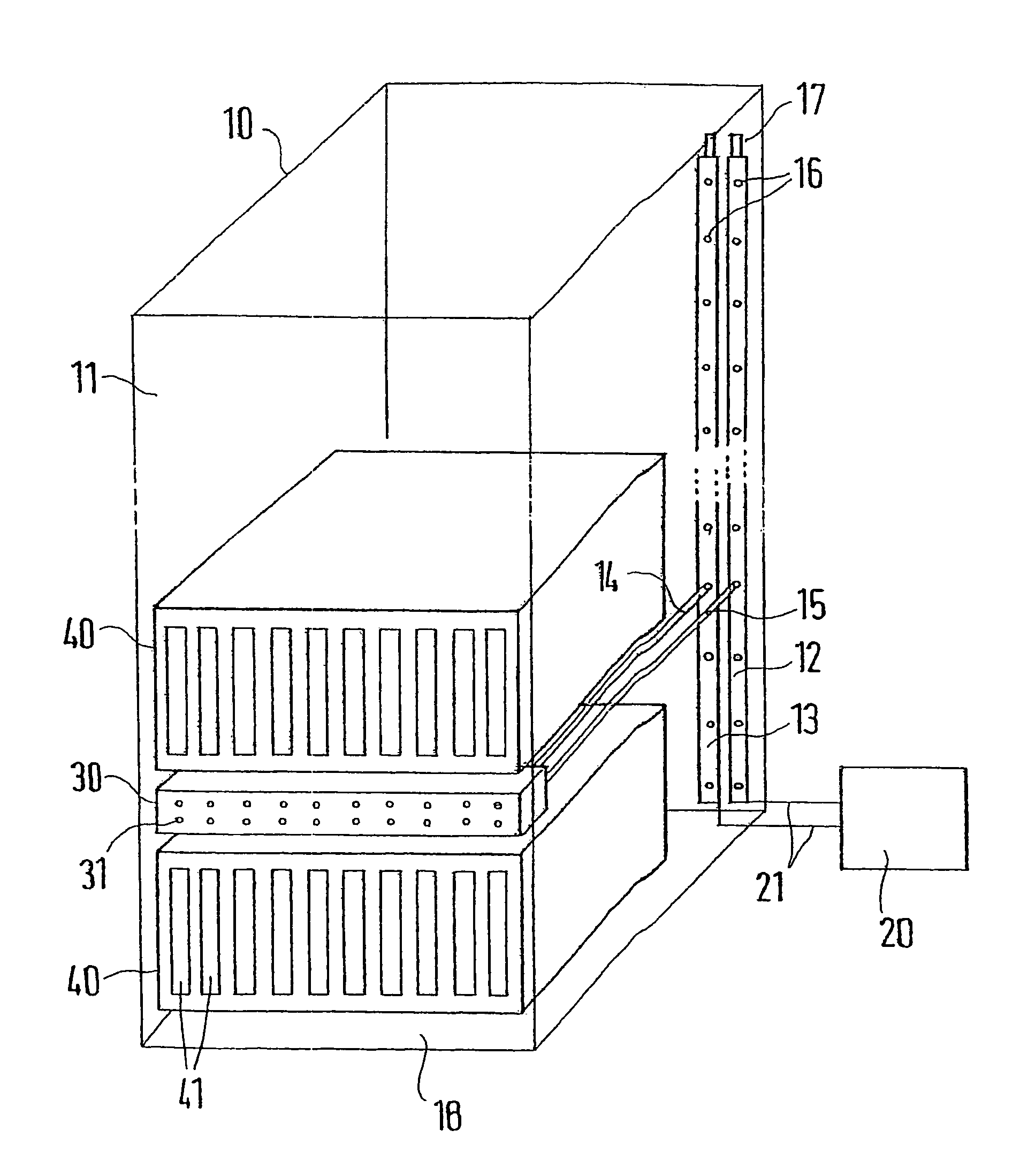
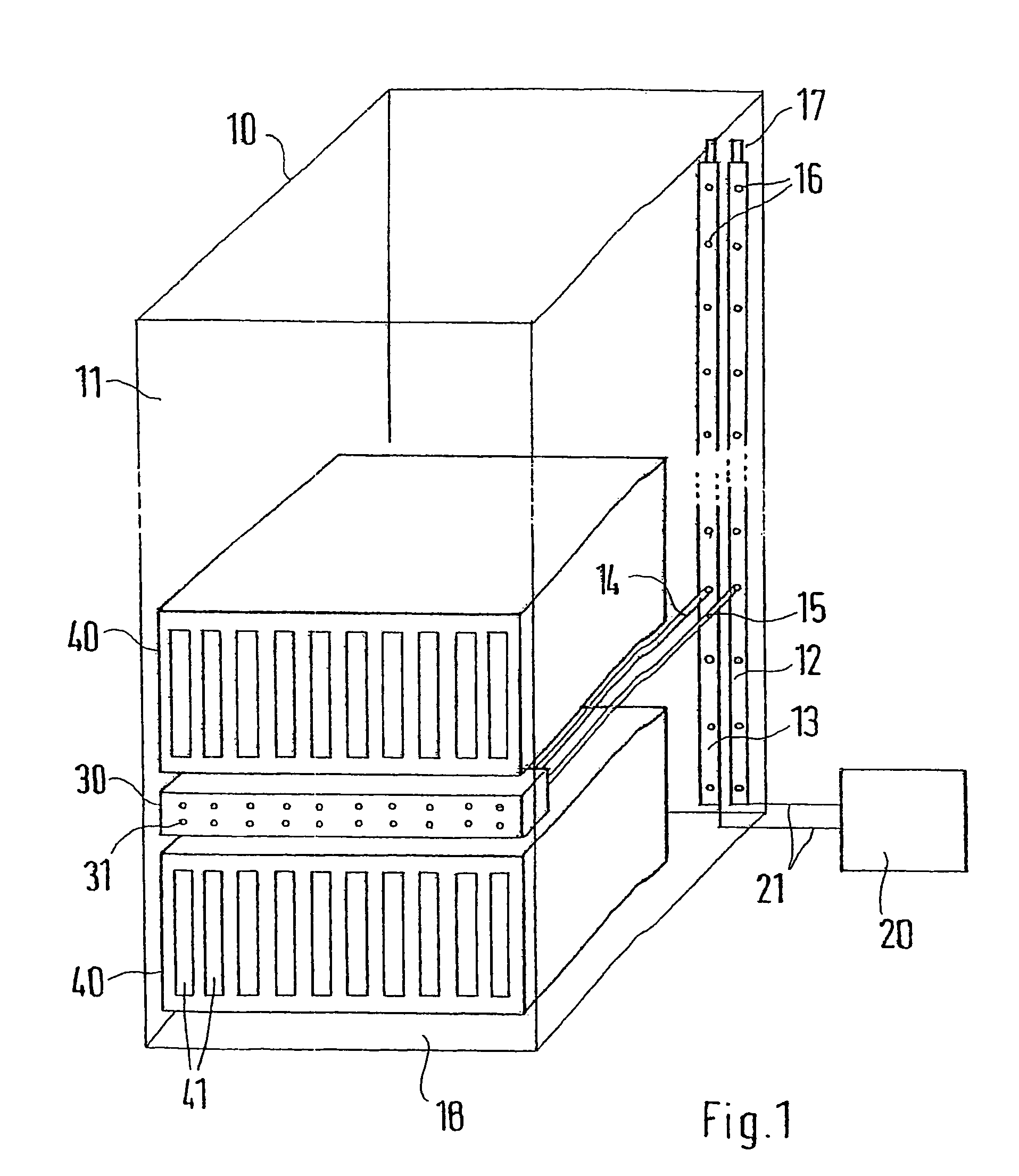
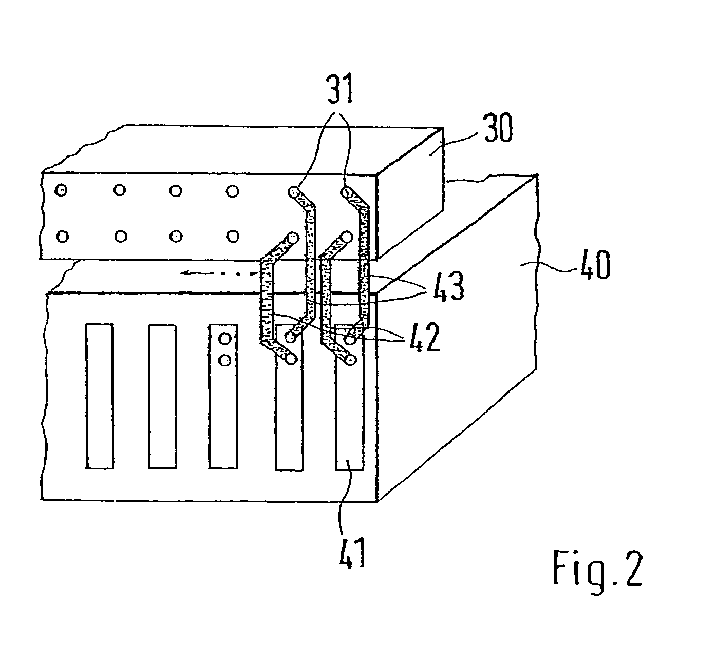
[0016]A receiver housing 10, which surrounds an interior 11, is shown in FIG. 1. Such receiver housings 10 are usually designed as switchgear cabinets having a rack. The rack is covered on all sides and is closed by a hinged door at the front 18. Built-ins are fastened to the rack in the interior 11. In the present case, servers 40, in particular blade servers, are maintained in the interior and have receptacles, in which the vertically oriented computer units 41, or power blade inserts, can be seated. A distributor 30 is arranged between the servers 40 and designed as a hollow profiled section with two chambers extending in longitudinal directions. The distributor 30, the same as the server 40, is accessible through the opened front 18 of the receiving housing 10. The distributor 30 can also be fastened on the rack and bridges the front 18 completely or partially.

[0017]The distributor 30 has distributor connectors 31, which are arranged in a graduated grid, spaced apart from each o...


PUM


Abstract

A housing arrangement including a receiving housing with an interior inside which a cooling device and one or several electric units are accommodated. The cooling device includes a flow line and a return line extending at least partially between the base area and ceiling area of the receiving housing. Connecting lines run from the flow line and the return line and are physically connected to a cooling circuit of one or several electric units. Effective cooling of receiving areas which are fitted in a complex manner with built-in components is obtained because a distributor line is respectively guided from a flow line and a return line to a distributor which is maintained inside the receiving housing. The distributor includes several distributor connections that can be connected to connection lines which are guided to the electric built-in component, such as a computer unit.

Description

BACKGROUND OF THE INVENTION[0001]1. Field of the Invention[0002]This invention relates to a housing arrangement with a receiver housing, an interior in which a cooling arrangement and one or several electrical units are housed, wherein the cooling arrangement has a feed line and a return line extending at least in parts between a bottom area and a ceiling area of the receiver housing, wherein connecting lines branch off the feed line and the return line and lead to at least one distributor arranged between the electrical units, and to distributor connectors connecting lines to the electrical units can be connected.[0003]2. Discussion of Related Art[0004]A housing arrangement is taught by U.S. Patent Publication 2002 / 0021557 A1. Here, a confused and hard to access conduct of the lines results from the conduct of the feed and return lines to the cooling arrangement, and of the connecting line to the distributor, as well as from the installed arrangement of the distributor and the elec...

Claims


Application Information

Patent Timeline
Patent Type & Authority Patents(United States)
IPC IPC(8): H05K7/20F28F7/00G06F1/18G06F1/20H01L23/473
CPCG06F1/181G06F1/20H05K7/20781G06F2200/201
Inventor DORRICH, MARTINNICOLAI, MICHAEL
Owner RITTALWERK RUDOLF LOH GMBH & CO KG
Learn More