
Method and system for radio detection and ranging intrusion detection system

a technology of intrusion detection and radio detection, applied in the field of intrusion detection systems, can solve the problems of limited information provided by current indoor surveillance radar systems, and achieve the effect of effective function

Active Publication Date: 2008-12-16
GE SECURITY INC
View PDF20 Cites 24 Cited by
  • Summary
  • Abstract
  • Description
  • Claims
  • Application Information

AI Technical Summary

Benefits of technology

[0042]State of the art intrusion RADAR systems are capable to sense and respond to the motion of a target. As used herein, the word “target” shall refer to any moving object the radar system is capable to detect, with the understanding that the most common “targets” are likely to be people walking throughout the monit

Problems solved by technology

Current indoor surveillance RADAR systems are limited to providing information relating only to the presence of motion within the monitored area.

Method used


Image

  • Method and system for radio detection and ranging intrusion detection system
  • Method and system for radio detection and ranging intrusion detection system
  • Method and system for radio detection and ranging intrusion detection system

Examples


Embodiment Construction

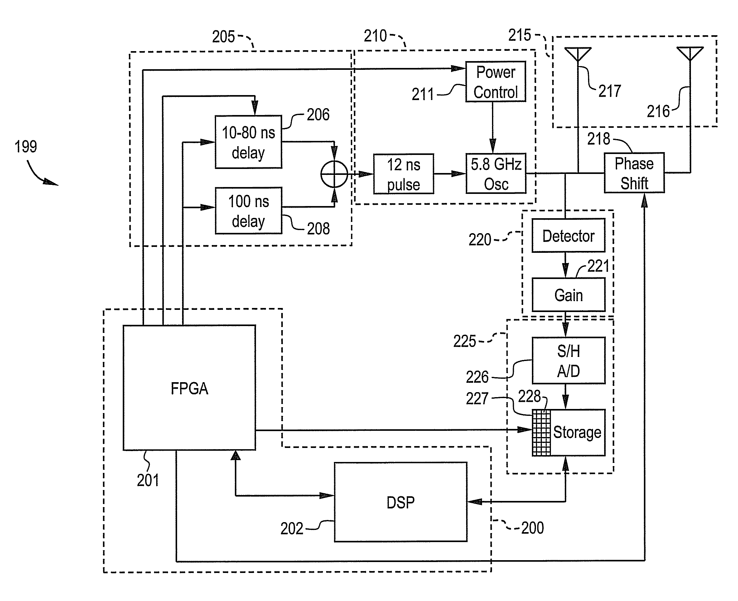
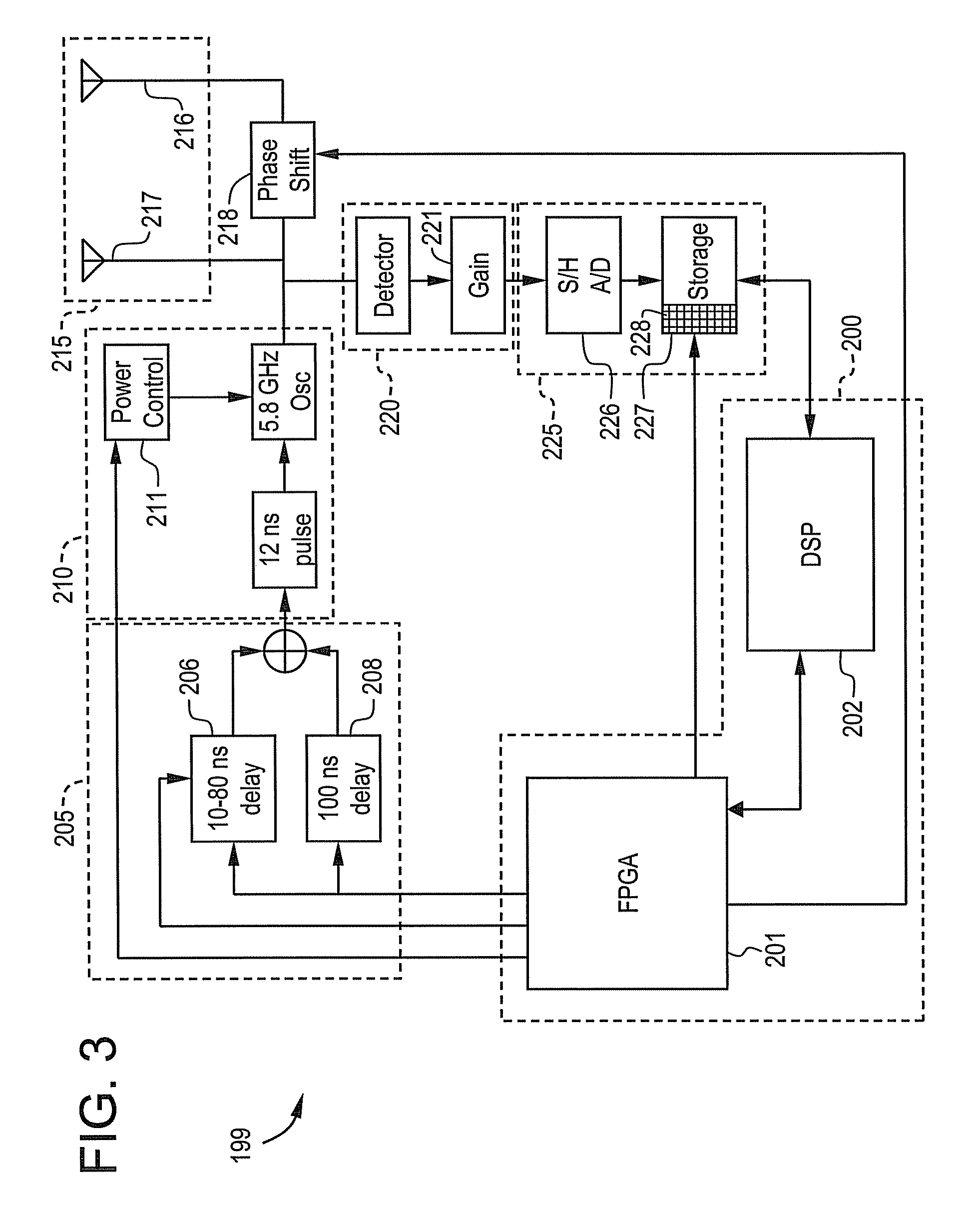
[0062]An embodiment of the invention will provide the capability of range estimation to a RADAR surveillance unit. An embodiment of the invention is a RADAR surveillance unit that is mounted in a fixed location, and is expected to detect and compute the range (distance from the RADAR system) of any moving target in its field of view. Another embodiment of the invention will be part of a tracking system that features multiple surveillance units and a central computer to keep track of individual targets. The multiple units of the system will have overlapping regions in which targets can be detected, and so the system will be able to locate targets by triangulation and knowledge of the environment (where the walls and doors are). To the extent that each surveillance unit can supply azimuthal angle information in addition to range information, a target location can be computed that is potentially more accurate than one based only on range. Because there may be so many radar returns in t...


PUM


Abstract

A RADAR system including a set of RADAR apparatuses is disclosed. Each apparatus includes a processor, a pulse unit in signal communication with the processor, a waveform signal generator in signal communication with the pulse unit, and a set of radar antennas in signal communication with the waveform signal generator. The waveform signal generator is capable of generating a waveform signal in response to pulses provided by the pulse unit. The set of antennas is capable of transmitting a burst of microwave energy in response to each waveform signal and to receive a plurality of reflected bursts associated with the transmitted bursts. An acquisition unit is configured to develop and amplify a finite window integral associated with each reflected burst, the acquisition unit in signal communication with the set of antennas and a pre-processor configured to digitize and store information relating to each finite window integral for subsequent processing.

Description

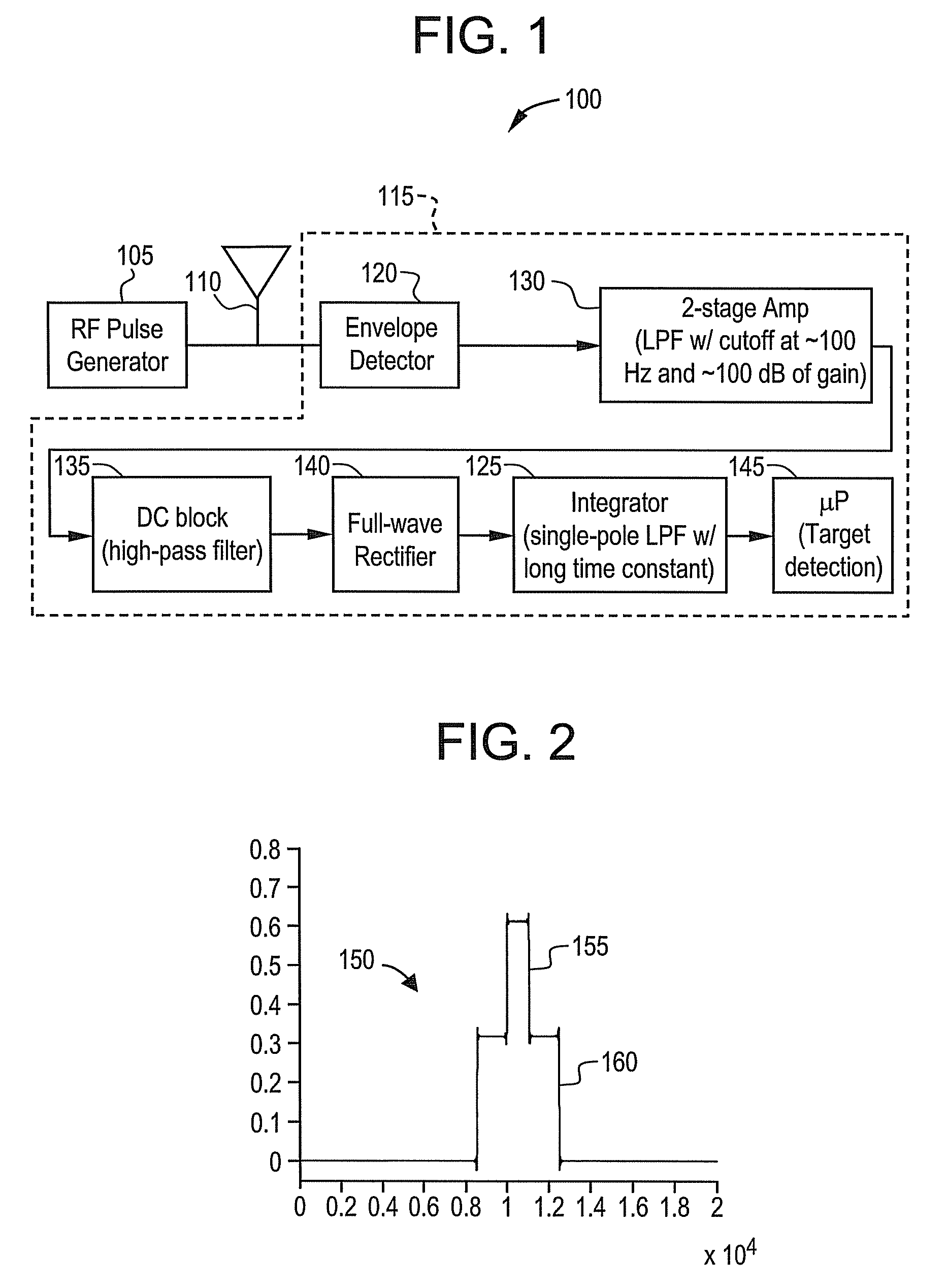
BACKGROUND OF THE INVENTION[0001]The present disclosure relates generally to intrusion detection systems, and particularly to radio detection and ranging (RADAR) intrusion detection systems.[0002]There is a need for indoor security devices to monitor areas subject to penetration by trespassers and also to alert authorities when personnel have entered a hazardous zone. One commonly employed technique is that of electromagnetic RADAR. It is well known in the art that a RADAR system may be used to monitor an area even though there is no direct visible line of sight from the RADAR unit to the area under surveillance, as a RADAR signal may often successfully penetrate and return through common building materials, thereby allowing the RADAR unit to be hidden or inconspicuous.[0003]Referring now to FIG. 1, a block schematic diagram of a basic signal processing operation is depicted. A baseline system 100 operates as a simple Pulsed Doppler radar using analog signal processing. A radio freq...

Claims


Application Information

Patent Timeline
IPC IPC(8): G01S13/12G01S13/10G01S13/00
CPCG01S7/288G01S13/12G01S13/56
Inventor HOCTOR, RALPH THOMASASHE, JEFFREY MICHAELSTAUDINGER, VINCENT PAULWELLES, KENNETH BRAKELEY
Owner GE SECURITY INC
Learn More