
Protective coverings for radiological equipment

a radiological equipment and protective covering technology, applied in the field of radiological equipment protective coverings, can solve the problems of patient nausea and regurgitation, difficult cleaning of material, and material sticky, and achieve the effect of preventing spillag

Inactive Publication Date: 2008-12-16
BATTLE RONALD K
View PDF2 Cites 8 Cited by
  • Summary
  • Abstract
  • Description
  • Claims
  • Application Information

AI Technical Summary

Benefits of technology

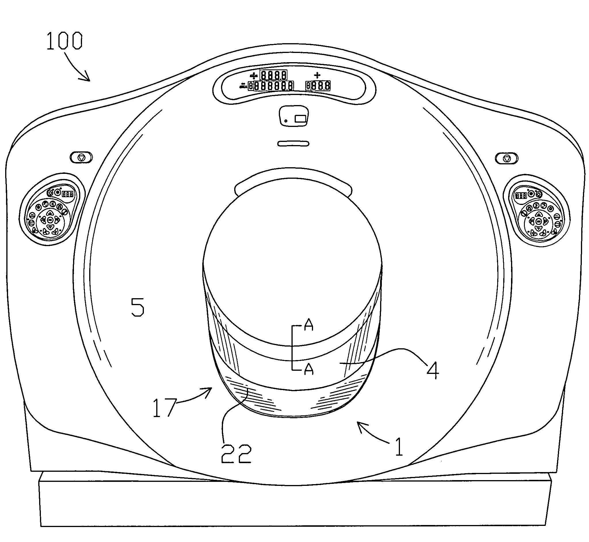
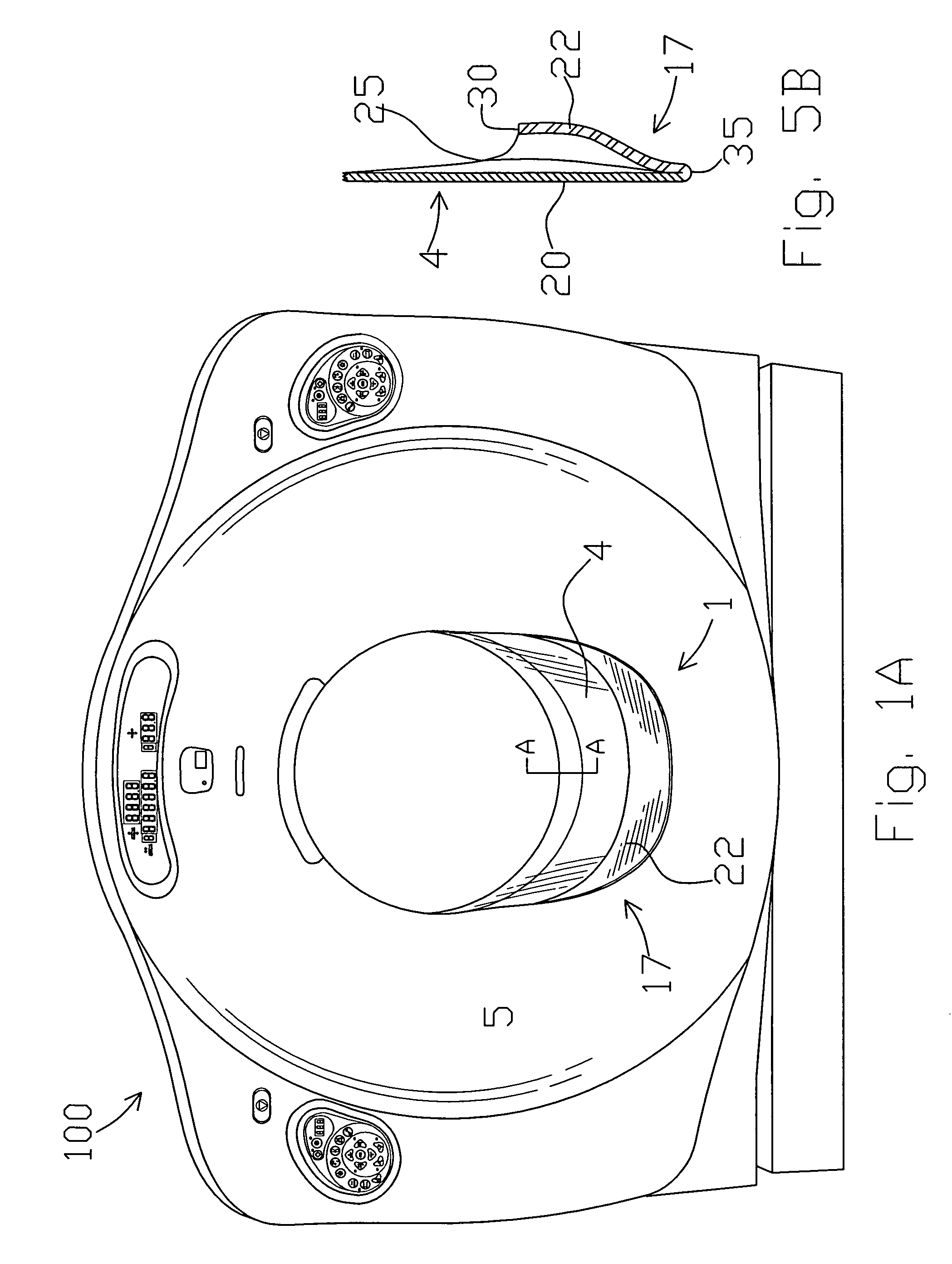
[0008]In one embodiment, the present invention is a disposable plastic covering that includes an inert adhesive material and semi-rigid seal that prevents fluids from entering the internal workings of a CT machine. The adhesive material fastens the seal region of the plastic covering across an opening between the plastic case and window arranged above the moving ring. An apron region of the plastic covering extends from within the central opening to direct fluids from within the machine. A second plastic covering is arranged on an opposite side of the window and seals the second seam. Either or both plastic coverings may include a pouch or pocket arranged at a bottom thereof for fluid collection and to further prevent spillage onto the scanner.
[0010]It is an object of the invention to provide a disposable plastic covering, a portion of which is secured above a moving ring of a CT scan machine, such that a seam that exists between an external casing of the CT scan machine and between a window of the CT scan machine is covered to prevent fluid from entering the machine.
[0011]It is another object of the invention to provide a cost effective means for preventing breakdowns of CT machines caused by fluid entering an unsealed region thereof.
[0013]It is an additional object of the invention to provide a means of reducing the spread of possible bio-hazard contaminants from a CT machine to technologists and patients. Thus, the present invention is a protective covering that is easily replaceable and a cost-effective method of reducing or preventing the spread of disease.
[0014]It is an added object of the invention to increase staff efficiencies of radiological personal by reducing cleaning and decontamination times when spills occur.
[0015]It is a supplemental object of the invention to prevent the introduction of biological hazardous agents and cleaning fluids into the gantry controls. This in turn, reduces electronic failure of the CT scanner and prevents the breeding and spreading of harmful pathogens.

Problems solved by technology

This contrast material is very sticky which creates difficulty in cleaning it up after a spill has occurred during the examination process.
Moreover, this material may cause the patient to become nauseous and regurgitate which tends to soil the machine.
In fact, patients who require CT scans are often sick, injured, or may become ill during the process resulting in body fluids, or like substances, from the patient being dispersed onto the CT machine.
Thus, these fluids may enter either of these seams and render the machine inoperable or contaminate the inner workings of the machine with body fluids.

Method used


Image

  • Protective coverings for radiological equipment
  • Protective coverings for radiological equipment
  • Protective coverings for radiological equipment

Examples


Embodiment Construction

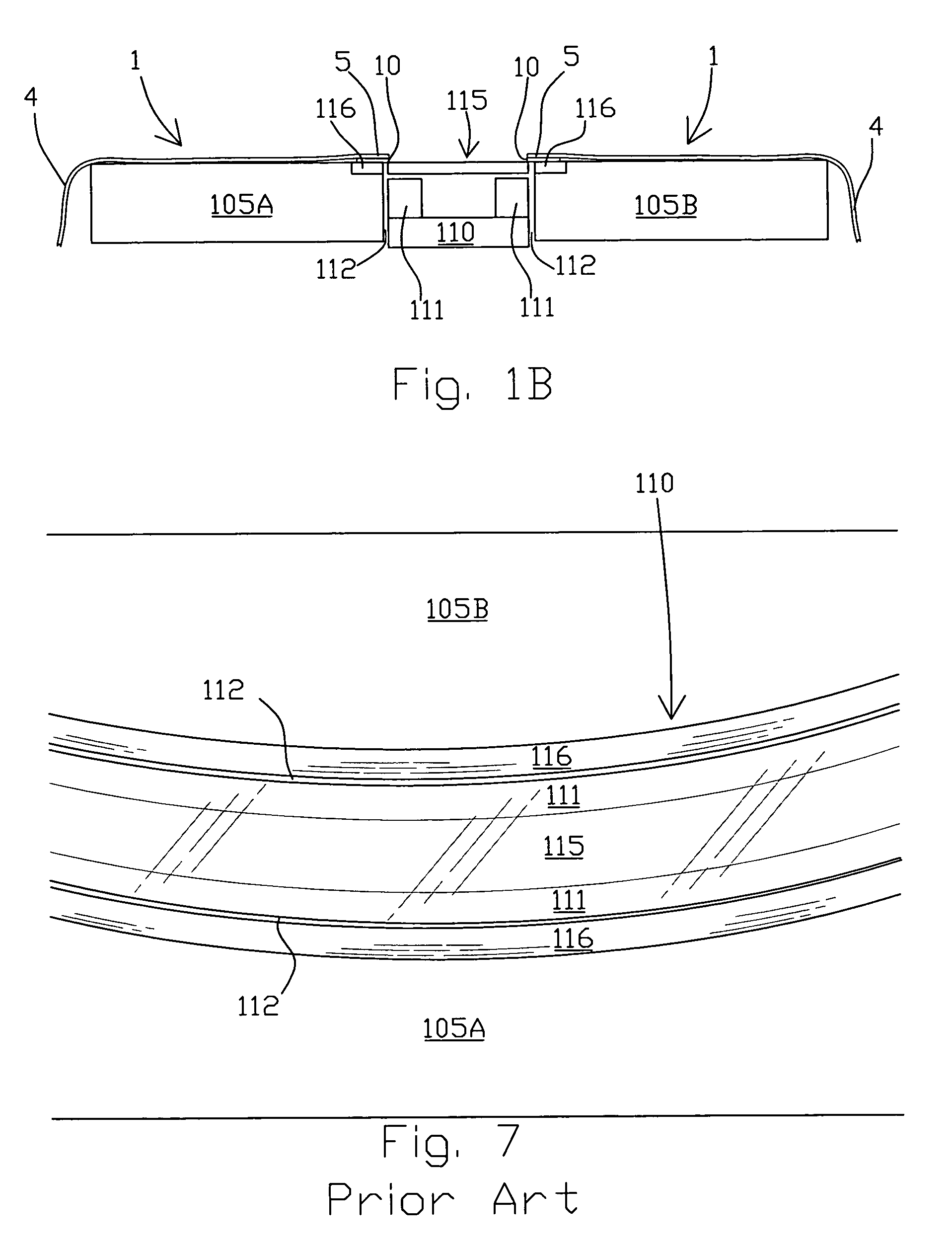
[0025]FIG. 2 shows a prior art CT scan machine 100 and associated table 125. The CT scan machine 100 includes a plurality of indicator lights 102 arranged above an inner opening 107 through which a patient or an area of the patient's body is passed. Controls 101 are arranged on opposite sides of the CT scan machine 100. A bed 125 is provided for passing the patient or his viewed part of body into the opening 107. As more clearly shown in the exploded view of FIG. 8, the CT scan machine 100 includes an external casing 105 that collectively comprises two halves 105A, 105B which are arranged on opposite sides of a movable ring 110. The halves of the external casing 105 protect the inner workings of the machine. For ease in understanding the invention, the other internal workings of the machine are not portrayed in FIG. 8.

[0026]FIG. 7 is a view of the movable ring 110 and external casing 105 taken from line A-A of FIG. 2. As shown in this Figure, opposite sides of the casing 105A, 105B ...


PUM


Abstract

A disposable plastic covering includes a seal region and an apron region for use in directing fluids away from an interior region of the machine to prevent the fluids from entering a CT machine. The covering includes an inert adhesive material for securing a seal. The adhesive material fastens the seal region of the plastic covering across an opening between an external casing and a window arranged above a moving ring upon which an X-ray emitter and detector are arranged. The apron region of the plastic covering extends from within a central opening of the CT machine to direct fluids from within the machine to an exterior of the machine. A second plastic covering is arranged on an opposite side of the window and seals the second seam. A further embodiment includes a pouch region in the disposable plastic covering for directing fluid therein. An additional covering is provided for controls of the machine.

Description

[0001]There are no related patent applications.[0002]The subject matter of the present invention did not receive federal government research and development funding.TECHNICAL FIELD[0003]The present invention is generally related to protective coverings for radiological equipment and prevents fluids from entering the inner workings of a CAT or CT machine. More specifically, the present invention is directed towards a removable, replaceable guard that seals openings and directs body fluids and other like substances away from the machine. The present invention provides a disposable covering for protecting a gantry of a radiological machine.BACKGROUND OF THE INVENTION[0004]A computerized axial tomography scan is commonly known as a CAT scan or CT scan. The CT scanning machine uses X-rays to make detailed pictures of various structures inside of a patient's body. The CT machine looks like a giant doughnut having a central opening and being tipped on its side. The machine includes a plast...

Claims


Application Information

Patent Timeline
Patent Type & Authority Patents(United States)
IPC IPC(8): H05G1/00H05G1/60
CPCA61B6/00A61B6/03
Inventor BATTLE, RONALD K.
Owner BATTLE RONALD K
Learn More