
Method and apparatus for delivering a biphasic defibrillation pulse with variable energy

a biphasic defibrillation and pulse technology, applied in electrotherapy, heart defibrillators, therapy, etc., can solve the problems of patient variability, transthoracic defibrillation problem, patient variability problem, etc., and achieve the effect of not fully addressing the transthoracic defibrillation problem nor the patient variability problem

Inactive Publication Date: 2008-12-09
ZOLL MEDICAL CORPORATION
View PDF48 Cites 10 Cited by
  • Summary
  • Abstract
  • Description
  • Claims
  • Application Information

AI Technical Summary

Problems solved by technology

However, this important advantage has two fundamental limitations.
This is known as the transthoracic defibrillation problem.
Second, external defibrillators must be able to be used on patients having a variety of physiological differences.
This is known as the patient variability problem.
The prior art described above effectively models implantable defibrillators, however it does not fully address the transthoracic defibrillation problem nor the patient variability problem.
In fact, these two limitations to external defibrillators are not fully appreciated by those in the art.
For example, prior art disclosures of the use of truncated exponential monophasic or biphasic shock pulses in implantable or external defibrillators have provided little guidance for the design of an external defibrillator that will successfully defibrillate across a large, heterogeneous population of patients.
Although the research determined a usable biphasic waveform, there was no new theoretical understanding determined for external waveform design.
The noted limitations of the transthoracic biphasic waveform may be due in part to a lack of principles-based design rules to determine its waveform characteristics.

Method used


Image

  • Method and apparatus for delivering a biphasic defibrillation pulse with variable energy
  • Method and apparatus for delivering a biphasic defibrillation pulse with variable energy
  • Method and apparatus for delivering a biphasic defibrillation pulse with variable energy

Examples


Embodiment Construction

[0031]The present invention provides a method and apparatus for tailoring a second phase (φ2) of a biphasic waveform delivered by an external defibrillator, to random patients, by performing intelligent calculations and analysis to the results of a first phase (φ1) segment of a biphasic defibrillation waveform and other parameters pertaining thereto. Prior to describing the present invention, a discussion of the development of an external defibrillation model will be given.

External Defibrillator Model

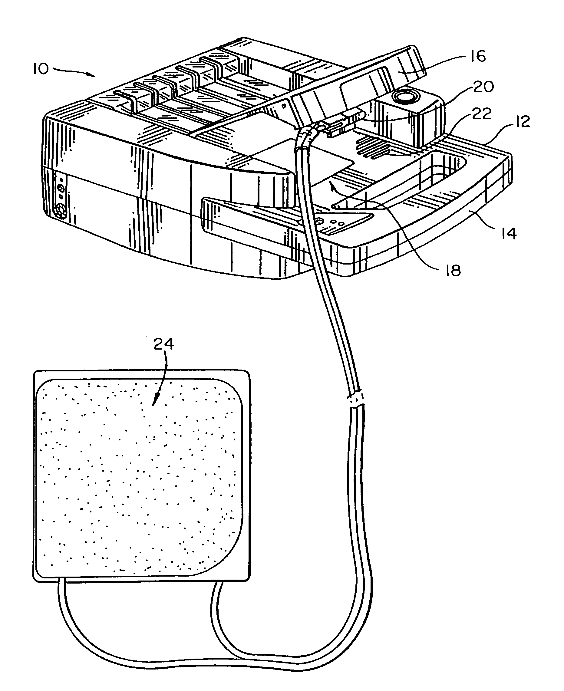
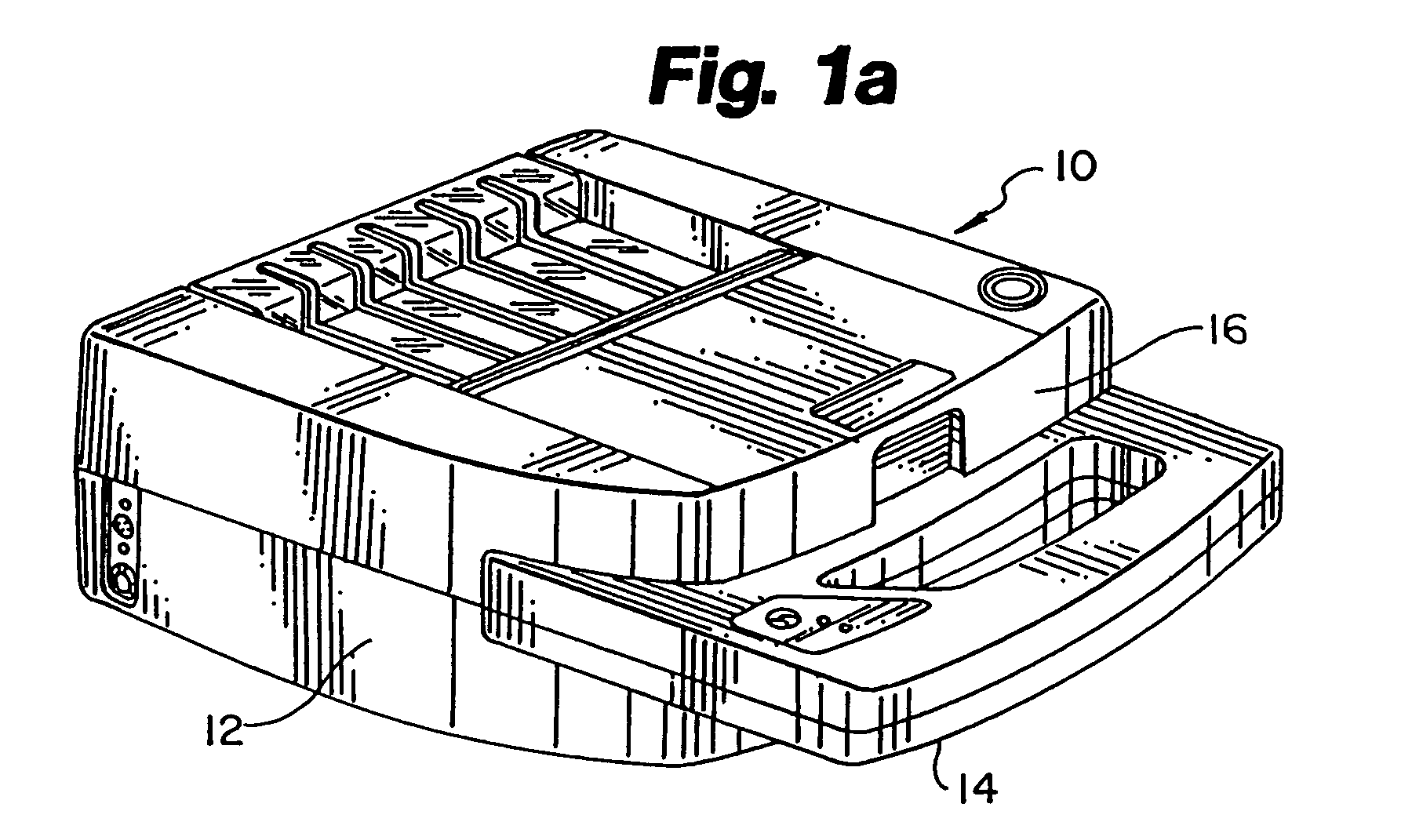
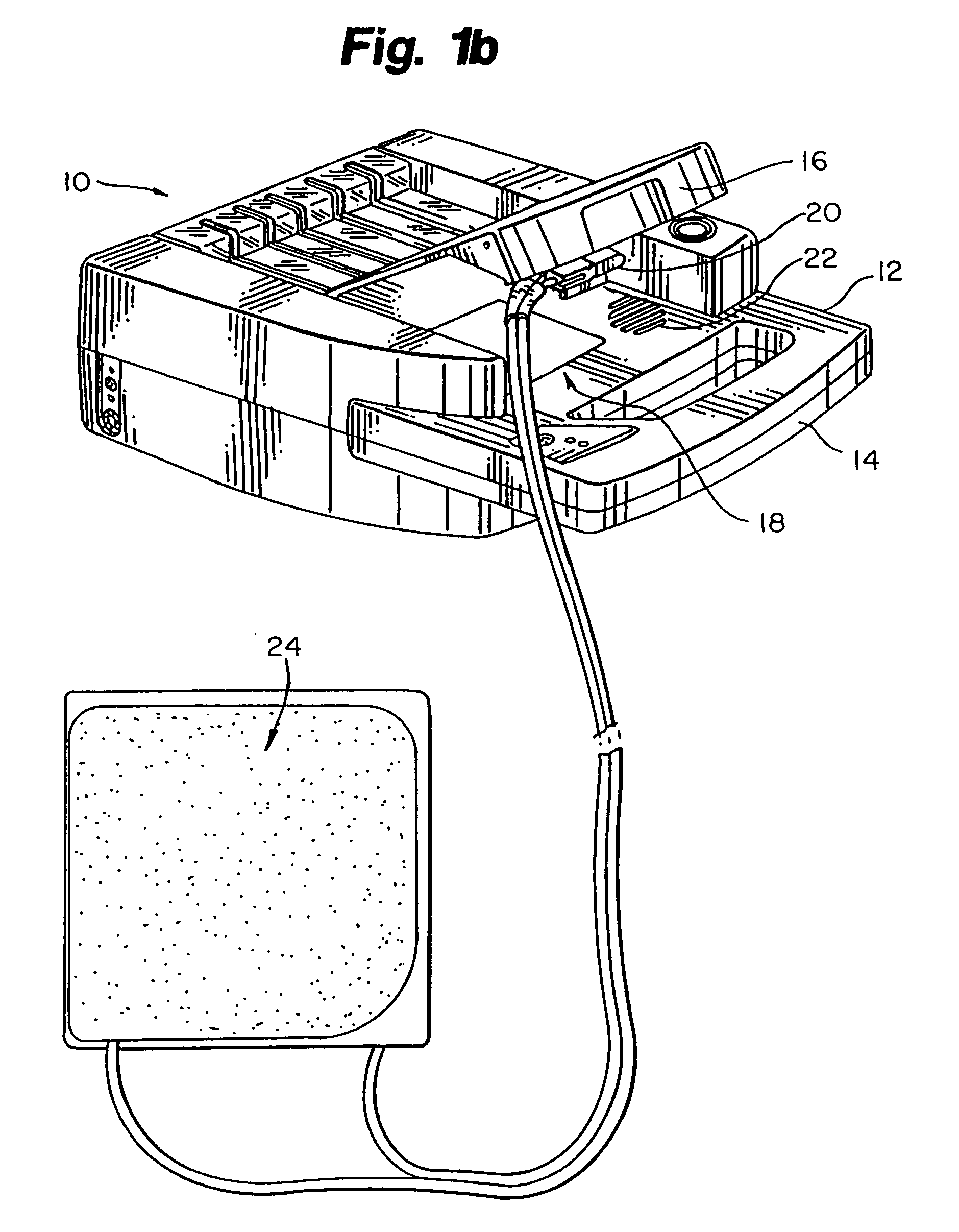
[0032]The apparatus of the present invention is an automated external defibrillator (AED) illustrated in FIGS. 1a and 1b. FIG. 1a illustrates an AED 10, including a plastic case 12 with a carrying handle 14. A lid 16 is provided which covers an electrode compartment 18. An electrode connector 20, a speaker 22 and a diagnostic panel (not shown) are located on case 12 within electrode compartment 18. FIG. 1b illustrates AED 10 having a pair of electrodes 24 connected thereto. Electrodes 2...


PUM


Abstract

An apparatus and method for determining an optimal transchest external defibrillation waveform that provides for variable energy in the first or second phase of a biphasic waveform that, when applied through a plurality of electrodes positioned on a patient's torso, will produce a desired response in the patient's cardiac cell membranes. The method includes the steps of providing a quantitative model of a defibrillator circuit for producing external defibrillation waveforms, the quantitative model of a patient includes a chest component, a heart component, a cell membrane component and a quantitative description of the desired cardiac membrane response function. Finally, a quantitative description of a transchest external defibrillation waveform that will produce the desired cardiac membrane response function is computed. The computation is made as a function of the desired cardiac membrane response function, the patient model and the defibrillator circuit model.

Description

RELATED APPLICATIONS[0001]This application is a continuation application of application Ser. No. 10 / 078,735, filed Feb. 19, 2002, now abandoned entitled “METHOD AND APPARATUS FOR DELIVERING A BIPHASIC DEFIBRILLATION PULSE WITH VARIABLE ENERGY,” which is a continuation application of non-provisional application Ser. No. 09 / 678,820, filed Oct. 4, 2000, now U.S. Pat. No. 6,411,846 entitled METHOD AND APPARATUS FOR DELIVERING A BIPHASIC DEFIBRILLATION PULSE WITH VARIABLE ENERGY, which is a continuation-in-part of application Ser. No. 09 / 383,561, filed Aug. 26, 1999, now U.S. Pat. No. 6,263,239 entitled METHOD AND APPARATUS FOR DETERMINING THE SECOND PHASE OF EXTERNAL DEFIBRILLATOR DEVICES, which is a continuation-in-part application of application Ser. No. 08 / 886,736 filed Jul. 1, 1997, now issued U.S. Pat. No. 5,968,080, which is based on provisional patent Application No. 60 / 021,161, filed Jul. 1, 1996 entitled DYNAMIC SECOND PHASE (φ2) WITH SELF-CORRECTING CHARGE BURPING FOR EXTERNAL...

Claims


Application Information

Patent Timeline
Patent Type & Authority Patents(United States)
IPC IPC(8): A61N1/39
CPCA61N1/39A61N1/3937A61N1/3912A61N1/3906A61N1/3904
Inventor BREWER, JAMES E.STENDAHL, GARY B.OLSON, KENNETH F.
Owner ZOLL MEDICAL CORPORATION
Learn More