Magnetic levitation weight reduction structure for a vertical wind turbine generator
a technology of wind turbine generator and magnetic levitation, which is applied in the direction of electric generator control, machines/engines, magnetic bodies, etc., can solve the problems of reducing the efficiency and speed of the fixed shaft supporting the hub, and achieve the effect of reducing the burden, reducing the resistance, and promoting the revolving efficiency and speed of the axl
- Summary
- Abstract
- Description
- Claims
- Application Information
AI Technical Summary
Benefits of technology
Problems solved by technology
Method used
Image
Examples
second embodiment
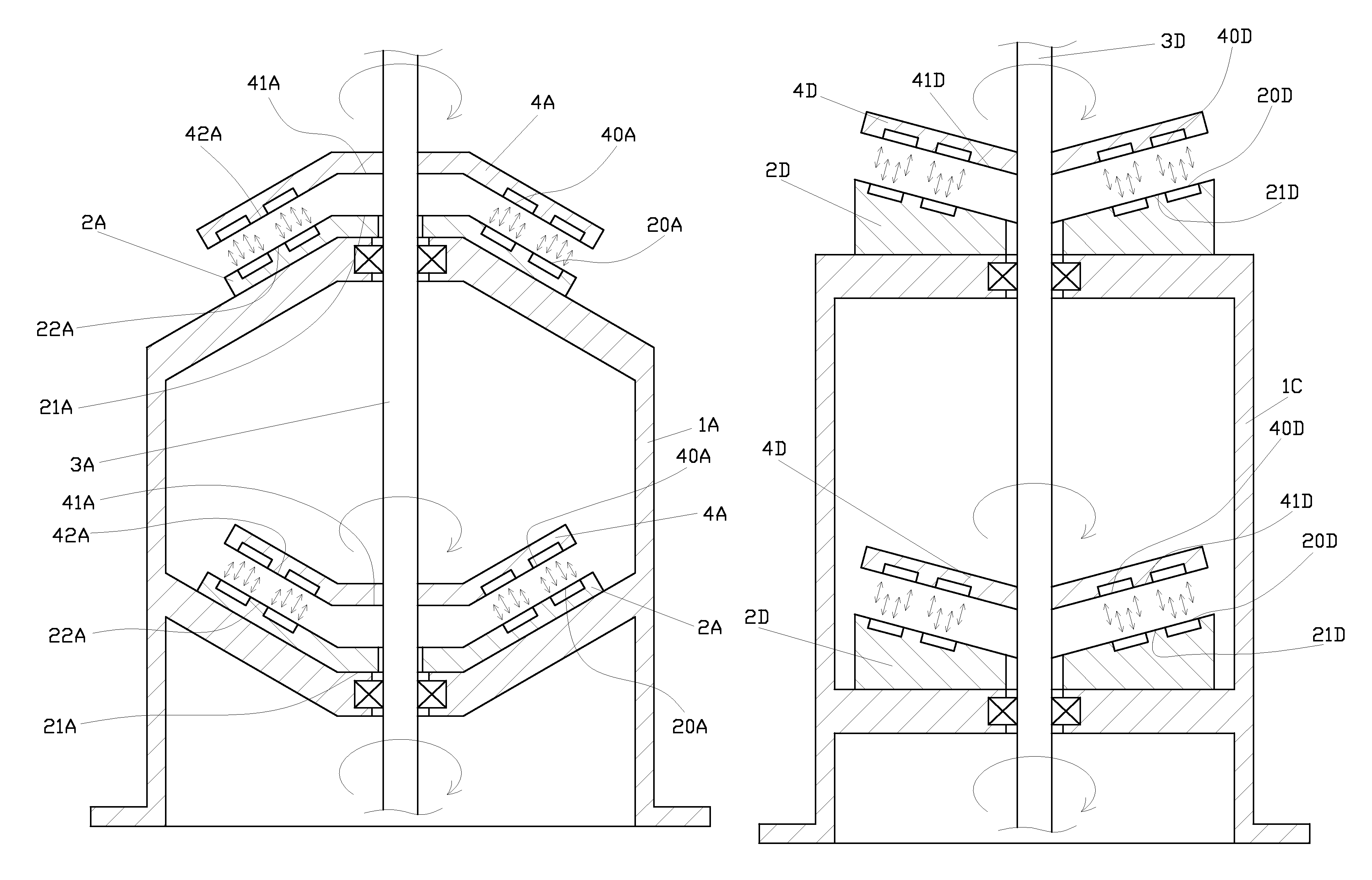
[0024]In the present invention as illustrated in FIG. 4, a fixed permanent magnet (2A) is fixed to a frame (1A). The fixed permanent magnet (2A) has a first repulsive surface (20A), a circular flat portion (21A) and an inclined portion (22A) extending from the circumference of the flat portion (21A). An axle (3A) is inserted through the frame (1A) and the fixed permanent magnet (2A). A revolving permanent magnet (4A) fixed to the axle (3A) has a second repulsive surface (40A), a flat portion (41A) and an inclined portion (42A) extending from the circumference of the flat portion (41A). Both the first repulsive surface (20A) of the fixed permanent magnet (2A) and the second repulsive surface (40A) of the revolving permanent magnet (4A) are assembled in the shape of a bowl. A repulsive force is created by the same magnetic pole of the fixed permanent magnet (2A) and the revolving permanent magnet (4A). When the blades are revolving for being subject to wind velocity, a repulsive force...
third embodiment
[0025]FIG. 5 shows the present invention. A fixed permanent magnet (2B) is fixed to a frame (1B). The fixed permanent magnet (2B) has a first repulsive surface (20B), a flat portion (21B) and a flange (22B) vertically extending from the circumference of the flat portion (21B). An axle (3B) penetrates through the frame (1B) and the fixed permanent magnet (2B). A revolving permanent magnet (4B) fixed to the axle (3B) has a second repulsive surface (40B), a flat portion (41B) and a flange (42B) vertically extending from the circumference of the flat portion (41B). Accordingly, the configuration between the fixed permanent magnet (2B) and the revolving permanent magnet (4B) indicates a reverse U-like shape; and a repulsive force is relatively produced by the same magnetic pole of the permanent magnet (2B) and the revolving permanent magnet (4B). Once the blades revolve for being subject to wind velocity, a repulsive force is relatively created between the vertical flange (22B) and the v...
PUM
 Abstract
Description
Claims
Application Information
 - R&D
- Intellectual Property
- Life Sciences
- Materials
- Tech Scout
- Unparalleled Data Quality
- Higher Quality Content
- 60% Fewer Hallucinations
Browse by: Latest US Patents, China's latest patents, Technical Efficacy Thesaurus, Application Domain, Technology Topic, Popular Technical Reports.
© 2025 PatSnap. All rights reserved.Legal|Privacy policy|Modern Slavery Act Transparency Statement|Sitemap|About US| Contact US: help@patsnap.com


