
Extendible and retractable actuator

a technology of extendable and retractable actuators, which is applied in the direction of lifting devices, vehicles with tipping movements, mobile jacks, etc., can solve the problems of difficult processing of conventional extendible and retractable actuators, high cost, and high cost of extending and retracting actuators, so as to reduce the extending and retracting time, simplify the structure, and reduce the cost

Active Publication Date: 2008-12-02
HIWIN MIKROSYST
View PDF8 Cites 23 Cited by
  • Summary
  • Abstract
  • Description
  • Claims
  • Application Information

AI Technical Summary

Benefits of technology

The present invention provides an extendible and retractable actuator that can extend and retract simultaneously at both ends, reducing the time and simplifying the structure. The actuator includes a sleeve assembly, a motor, screws, and a gear box. The motor is connected to one end of the sleeve assembly, and the shaft of the motor protrudes out of both ends. The first screw is connected to the shaft of the motor and engaged with the sleeve assembly. The gear box and motor are in the same sleeve, and the second screw is fixed to the other end of the sleele assembly. The actuator has the advantages of simple structure, high strength, and low cost.

Problems solved by technology

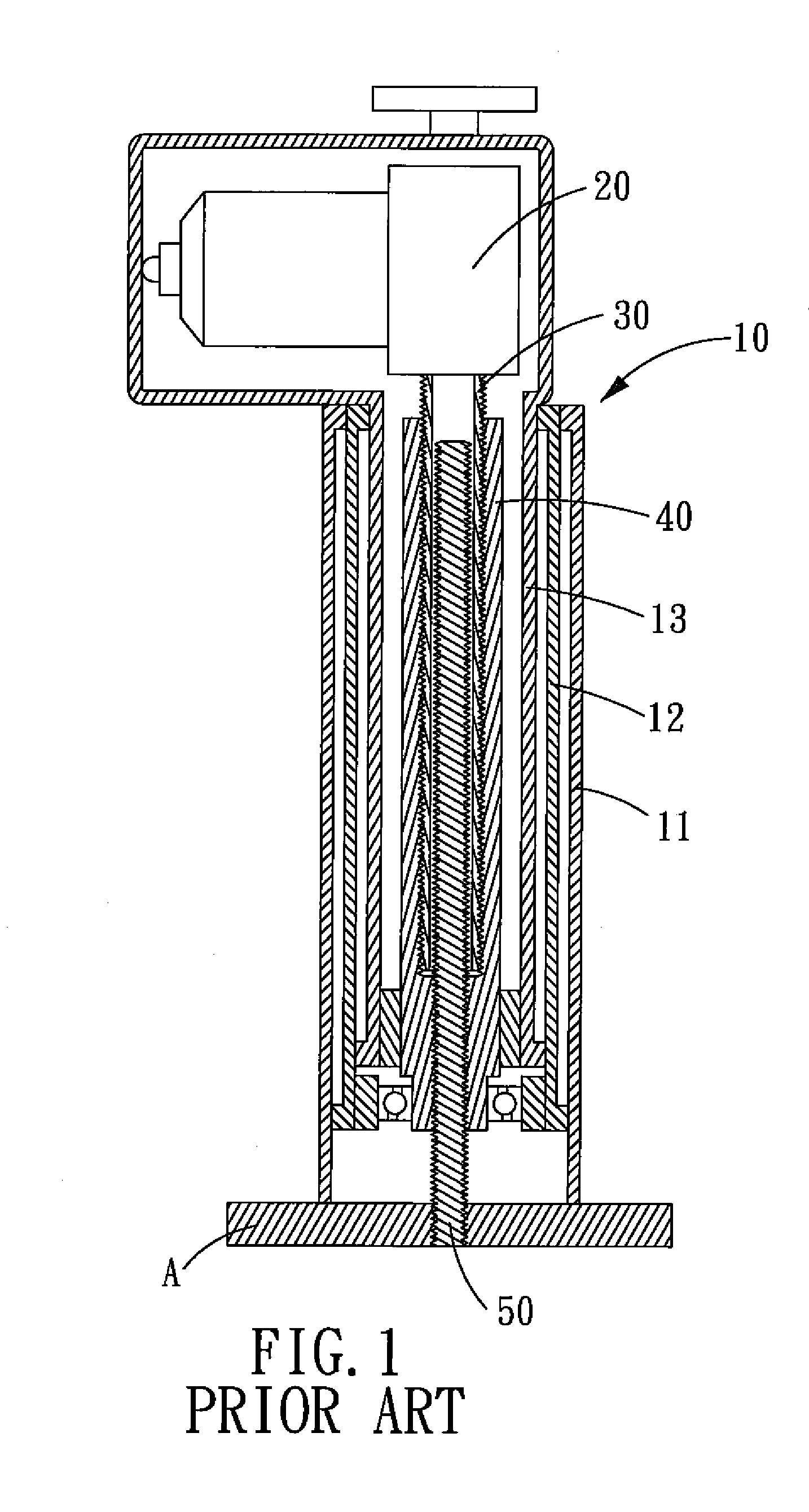
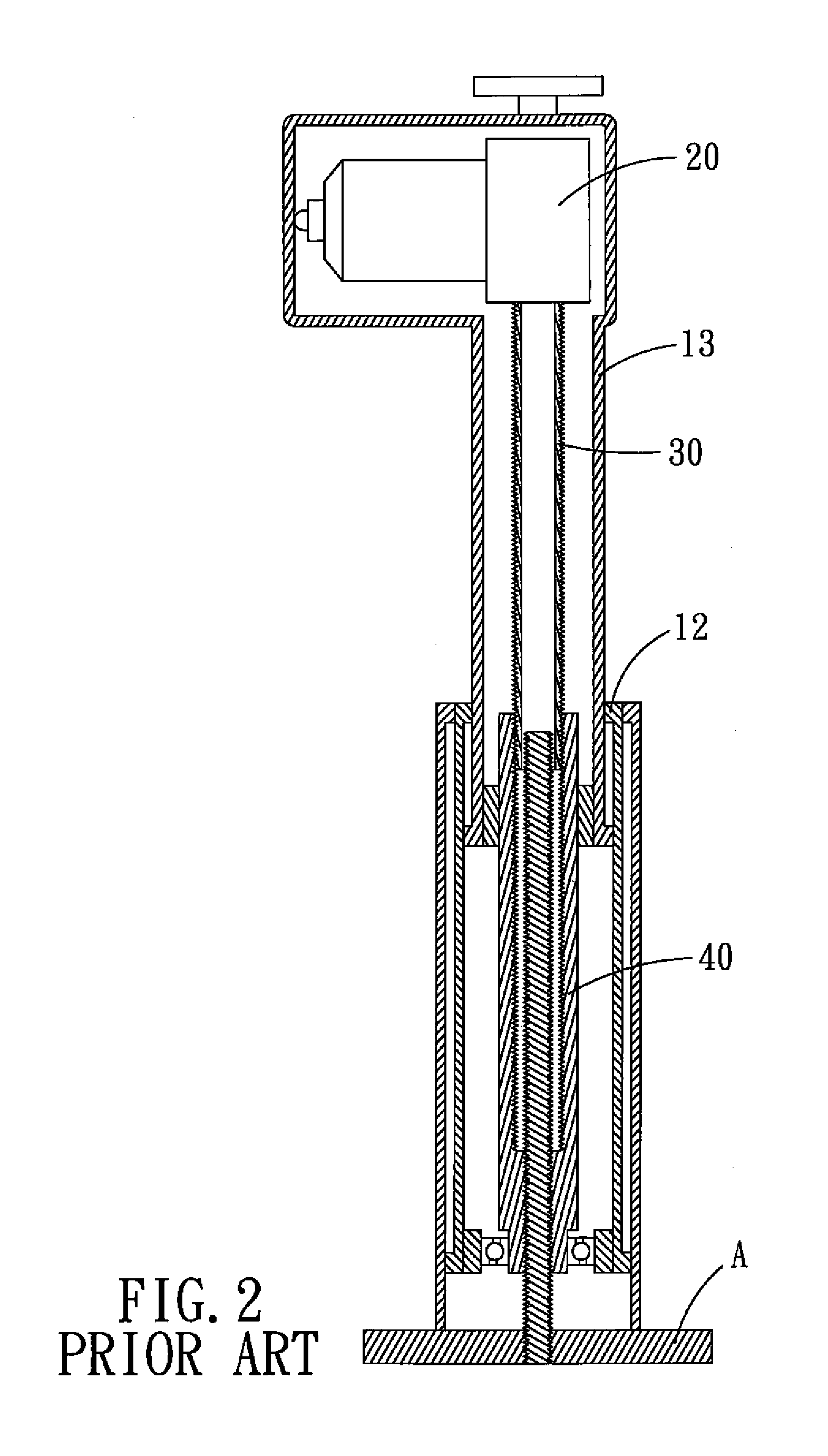
Firstly, the extending and retracting motion of the extendible and retractable actuator takes a lot of time, since the middle sleeve 12 can be driven to extend only when the inner sleeve 13 extends to the end of maximum travel length.
Secondly, the components of the conventional extendible and retractable actuator are likely to be damaged, since the second screw 40 can be driven to rotate only when the first screw 30 rotates to the end of maximum travel length.
Thirdly, the conventional extendible and retractable actuator is difficult to process, since the first screw 30 must be hollow and defined with outer threads, and the second screw 40 must be defined with inner threads to be engaged with the outer threads of the first and the third screws 30 and 50.
Secondly, the components of the conventional extendible and retractable actuator are likely to be damaged, since the middle sleeve 12 and the inner sleeve 13 can be moved simultaneously only when the rope 61 winds around the wheel 60, the force applied on the rope 61 is quiet big, and the rope 61 will be broke if the force is too big.
In addition, the rope 61 can be replaced by chain, however, the chain can also cause abrasion to the wheel 60.

Method used


Image

  • Extendible and retractable actuator
  • Extendible and retractable actuator
  • Extendible and retractable actuator

Examples


Embodiment Construction

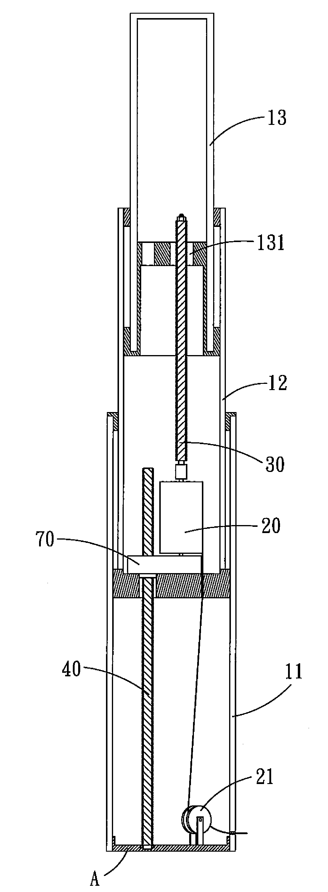
[0034]Referring to FIG. 6, an extendible and retractable actuator in accordance with the present invention comprises: a base A, an extendible and retractable sleeve assembly 10, a motor 20, a first screw 30, a second screw 40 and a gear box 70.

[0035]The extendible and retractable sleeve assembly 10 includes an outer sleeve 11, a middle sleeve 12 and an inner sleeve 13. One end of the outer sleeve 11 is fixed to the base A, and a screw 131 is fixed in the inner sleeve 13.

[0036]The motor 20 is mounted in the middle sleeve 12 of the extendible and retractable sleeve assembly 10, and the shaft of the motor 20 protrudes out of both ends of the middle sleeve 12. A roller 21 with elastic restoration force is fixed to the base A. The power wire of the motor 20 winds around the roller 21 and is connected to the power source after passing through the outer sleeve 11.

[0037]One end of the screw 30 is connected to one end of the shaft of the motor 20, the first screw 30 extends toward the interi...


PUM


Abstract

An extendible and retractable actuator comprises a motor, two screws and an extendible and retractable sleeve assembly. The motor cooperates with the screws to drive the extendible and retractable sleeve assembly to extend and retract simultaneously, so as to reduce the extending and retracting time and to simplify the structure of the extendible and retractable actuator.

Description

BACKGROUND OF THE INVENTION[0001]1. Field of the Invention[0002]The present invention relates to a motion transmission device, and more particularly to an extendible and retractable actuator.[0003]2. Description of the Prior Art[0004]The use of actuators are quite extensive, a motor of one kind of the actuators is mounted in an extendible and retractable sleeve and drives the sleeve to extend and retract, and then the extending and retracting motion of the sleeve drives other mechanisms to move.[0005]Referring to FIG. 1, a conventional extendible and retractable actuator comprises a base A, an extendible and retractable sleeve assembly 10, a motor 20, a first screw 30, a second screw 40 and a third screw 50. The sleeve assembly 10 includes an outer sleeve 11, a middle sleeve 12 and an inner sleeve 13. One end of the outer sleeve 11 is fixed to the base A, and the motor 20 is fixed in the inner sleeve 13 of the sleeve assembly 10. The first screw 30 is a hollow member defined with ou...

Claims


Application Information

Patent Timeline
Patent Type & Authority Patents(United States)
IPC IPC(8): B66F3/18
CPCB66F3/10
Inventor CHEN, TUNG-HSINYANG, BING-HONG
Owner HIWIN MIKROSYST
Learn More