
Surgical stapler with sound producing mechanism to signal the completion of the stapling process

a technology of sound producing mechanism and surgical stapler, which is applied in the direction of surgical staples, paper/cardboard containers, applications, etc., can solve the problems of not being able to tell how hard the movement will become and the user gets no particular sensation

Active Publication Date: 2008-12-02
MATSUTANI SEISAKUSHO CO LTD
View PDF32 Cites 292 Cited by
  • Summary
  • Abstract
  • Description
  • Claims
  • Application Information

AI Technical Summary

Benefits of technology

[0017]Accordingly, the present invention is conceived as a solution to the above-described problems of the conventional art, and has as its object to provide a surgical stapler that enables the user to sense clearly the suturing operation, that is, the completion of the bending of the staple.
[0031]According to the present invention, when the bending of the staple into its final form is completed, one member strikes another member so as to produce a vibration or a sound, thereby enabling the user of the surgical stapler to sense clearly that suturing is completed so as to prevent stopping of the stapling before the staple is fully bent in place and the suture is completed.

Problems solved by technology

However, the surgical staplers described in Japanese Laid-Open Patent Application Publication Nos. 5-3879 and 2000-217829 suffer from the drawback that the user gets no particular sensation indicating that the staple has been bent into its final form when that action is completed as shown in FIG. 3C.
However, after the movement of the trigger 25 gets easier it is not easy to tell how hard the movement will become, and it is easy to think that the suture is completed when in fact it is not.

Method used


Image

  • Surgical stapler with sound producing mechanism to signal the completion of the stapling process
  • Surgical stapler with sound producing mechanism to signal the completion of the stapling process
  • Surgical stapler with sound producing mechanism to signal the completion of the stapling process

Examples


Embodiment Construction

[0038]Preferred embodiments of the present invention will now be described in detail, with reference to the accompanying drawings.

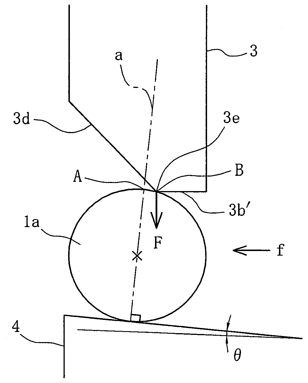
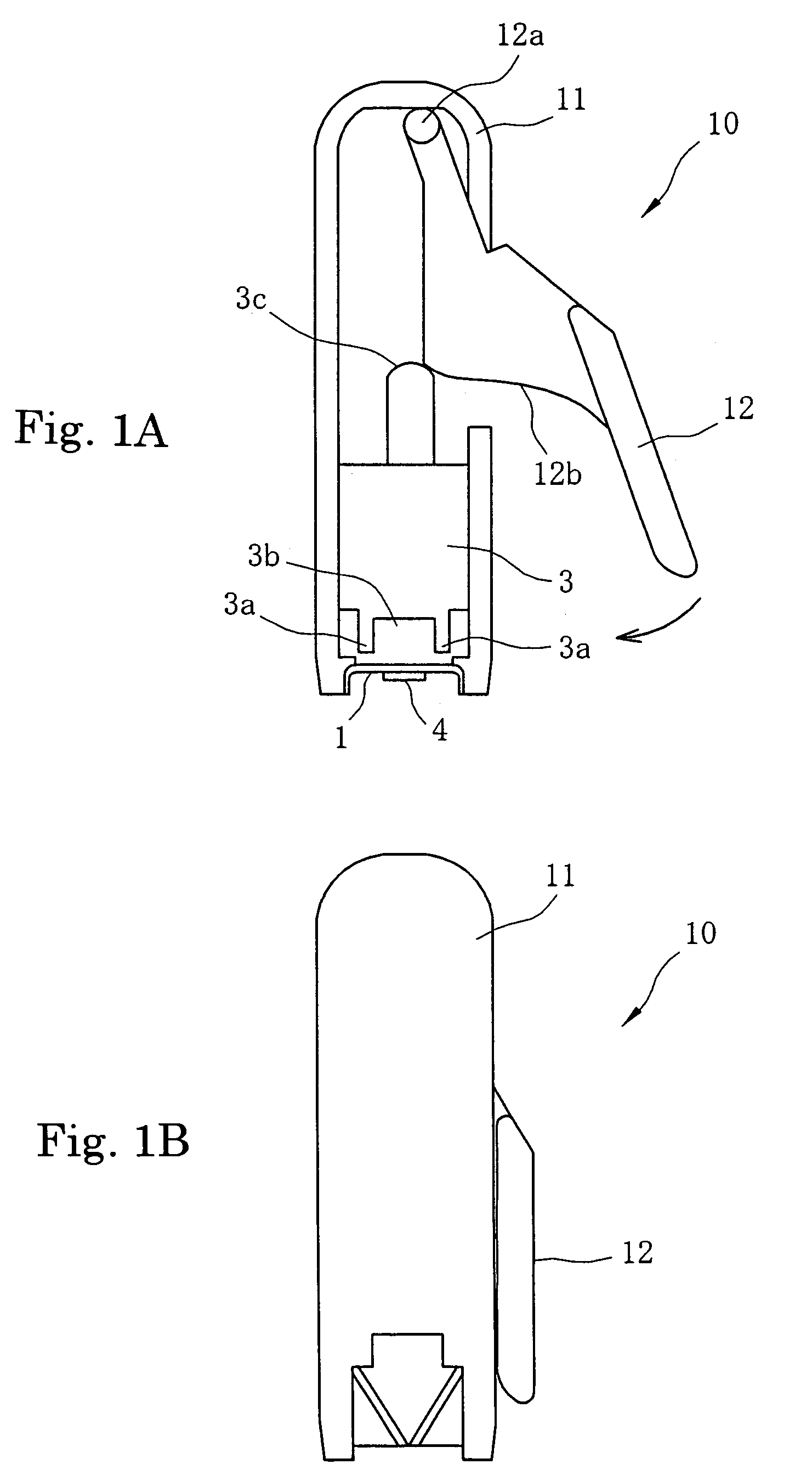
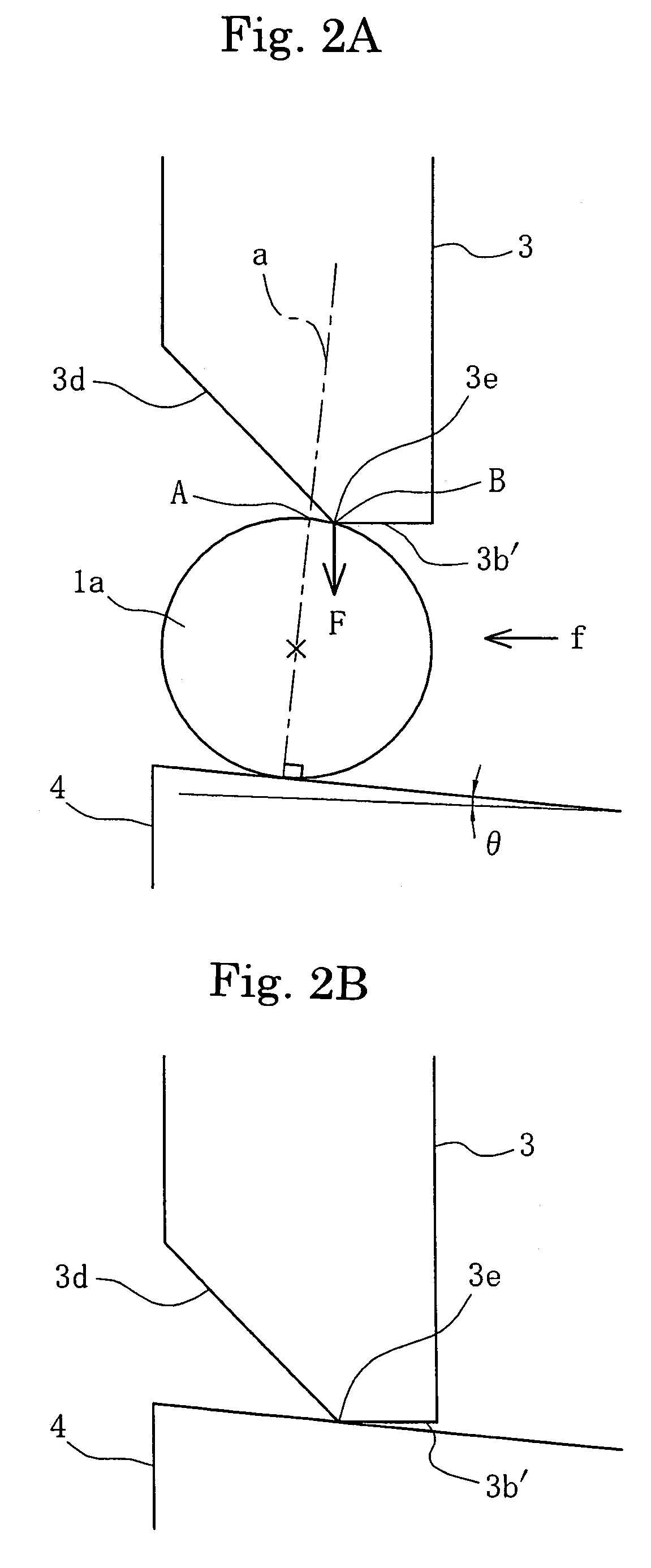
[0039]FIGS. 1A and 1B are diagrams showing the surgical stapler shown in the conventional example shown in FIG. 4 improved to achieve the object of the present invention, with FIG. 1A showing the surgical stapler prior to bending of the staple and FIG. 1B showing the surgical stapler in a state in which the bending of the staple is completed.

[0040]With a surgical stapler 10 shown in FIGS. 1A, 1B, one end of a trigger 12 is supported within a body 11 of the surgical stapler 10 so as to rotate freely. A plate cam 12b is formed on the trigger 12, and when the trigger 12 revolves clockwise around a shaft 12a, the plate cam 12b presses a projection 3c on a ram 3 and the ram 3 moves downward in the diagram. When the force applied to the trigger 12 is released, the ram 3 returns upward impelled by the force of a spring, not shown, and the trigger 12 revolves cou...


PUM

PropertyMeasurementUnit
diameteraaaaaaaaaa
structureaaaaaaaaaa
forceaaaaaaaaaa

Abstract

A surgical stapler has a body capable of containing a plurality of staples in an aligned state; a ram provided inside the body, having a central concave portion and pressure armatures on both sides of the concave portion; an anvil that, when the armatures of the ram contact both sides of a crown of a staple, forces the center of the crown into the concave portion of the ram; and a trigger rotatably supported on the body so as to cause relative movement between the ram and the anvil. The trigger as a moving member and the body as another member strike each other so as to produce a sound and / or a vibration indicating that a staple sandwiched between the ram and the anvil is bent by the advance of the anvil into the concave portion of the ram and bending of the staple is completed.

Description

BACKGROUND OF THE INVENTION[0001]1. Field of the Invention[0002]The present invention relates to a surgical stapler for suturing tissue, and more particularly, to a surgical stapler that enables the user to sense clearly the suturing operation, that is, the completion of the bending of the staple.[0003]2. Background of the Invention[0004]In surgical operations, metal staples are bent to suture shut an incision. As that which is used for this purpose, the surgical staplers described in Japanese Laid-Open Patent Application Publication No. Heisei 05-3879 and Japanese Laid-Open Patent Application Publication No. 2000-217829 are conventionally known.[0005]FIG. 3 shows the process of bending a staple using these conventionally known surgical staplers.[0006]A staple 1 penetrates the tissue and remains imbedded in the tissue until the incision heals. Accordingly, it is important that the staples be both sufficiently strong and do not adversely affect the tissue, and for these reasons auste...

Claims


Application Information

Patent Timeline
Patent Type & Authority Patents(United States)
IPC IPC(8): A61B17/068
CPCA61B17/0684A61B2019/2292A61B2019/4857A61B34/76A61B2090/0811
Inventor MATSUTANI, KANJIFUKUDA, MASATOSHIKAMEI, TOSHIHARUINA, TAKASHI
Owner MATSUTANI SEISAKUSHO CO LTD
Learn More