Color wheel

a color wheel and wheel body technology, applied in the field of color wheels, can solve the problems of reducing the operational reliability adversely affecting the operation of the color wheel, and so as to reduce the difficulty of positioning in this invention, the effect of reducing the impact of centrifugal force on the counterpoise and further reducing the vibration and noise caused by the color wheel

Inactive Publication Date: 2008-11-18
TRANSAKT
View PDF5 Cites 0 Cited by
  • Summary
  • Abstract
  • Description
  • Claims
  • Application Information

AI Technical Summary

Benefits of technology

[0012]As mentioned above, the invention provides a color wheel, in which an added counterpoise is positioned within a specific recess formed by the spacer, so that the position of the rotation center may be corrected. Compared to the prior art, the difficulty of positioning in this invention may be decreased by fitting or adhering the counterpoise into the specific recess of the color wheel. Furthermore, since the counterpoise may be placed totally within the recess, it is free from collisions. Also, the influence on the counterpoise caused by centrifugal force is reduced. Moreover, since the rotation center of the color wheel may be corrected, the vibration and noise caused by the color wheel is further reduced, and the operational reliability is also improved. In addition, since the spacer is the transparent substance and it can be irradiated by light, the binding time of the color filter, the spacer and the housing is further reduced, and the fabrication cost is also reduced. Besides, a specific groove is formed in the spacer, and the groove may absorb an excess of adhesive between the color filter and the spacer. In other words, an excess of adhesive may flow into the groove, so that the pollution of the color filter caused by the adhesive is avoided. Then, the definition and the clear scope of the color filter are improved.

Problems solved by technology

When the rotation center of the motor is away from the central axis of the rotation shaft (i.e., when the rotation center is not located on the central axis of the rotation shaft), the operation of the color wheel may be adversely influenced by vibration and noise.
Further, the operational reliability of the color wheel may decrease.

Method used


Image

  • Color wheel
  • Color wheel
  • Color wheel

Examples


Embodiment Construction

[0019]The color wheel in accordance with preferred embodiments of the invention will be described with reference to the accompanying drawings.

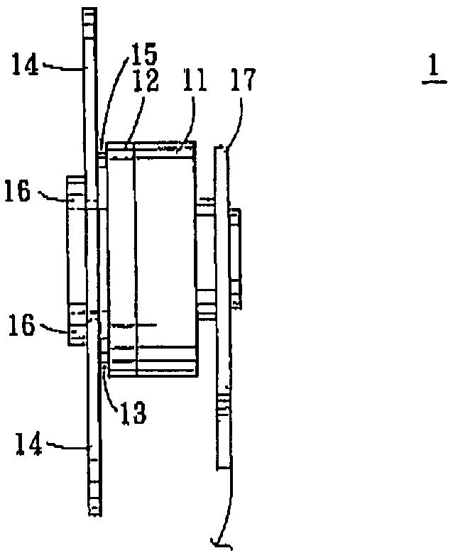
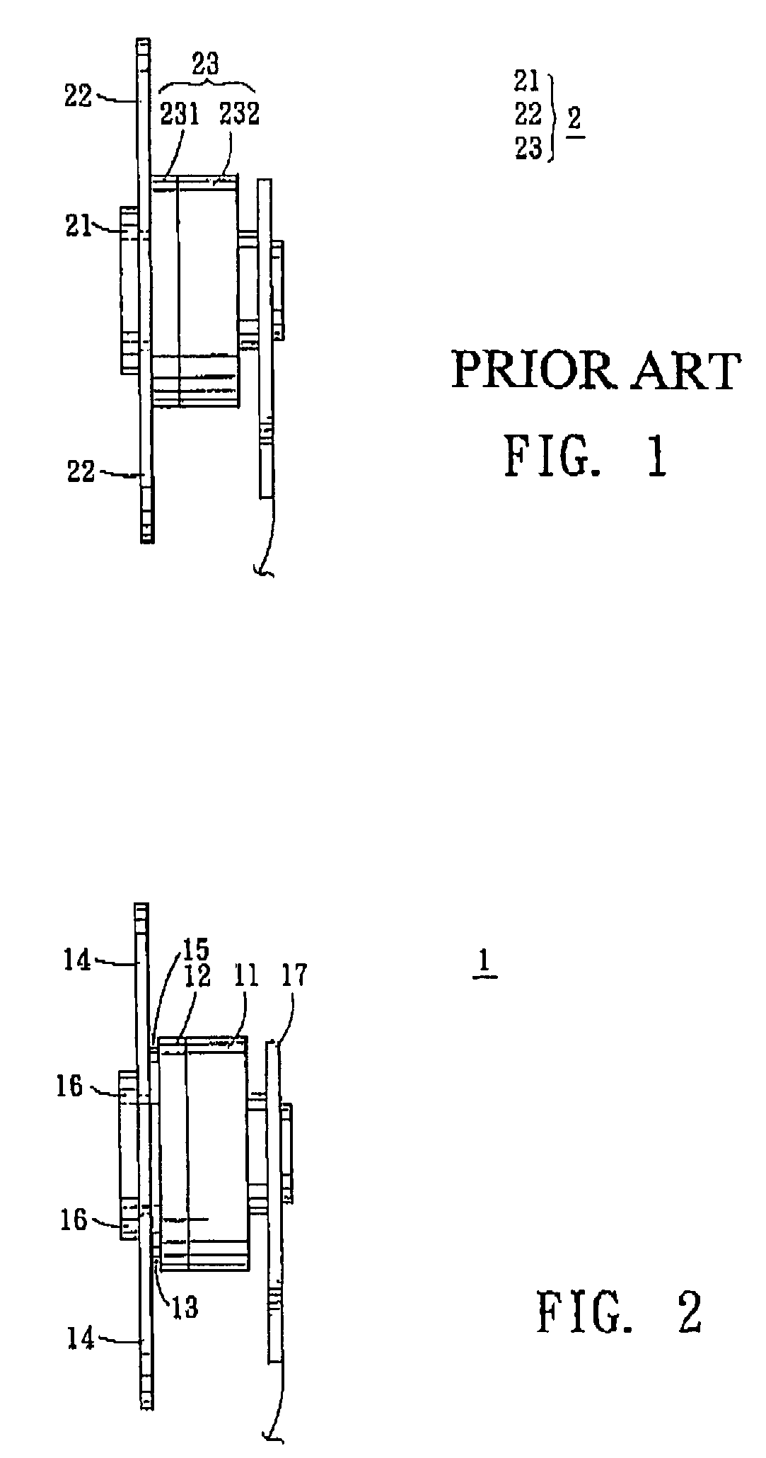
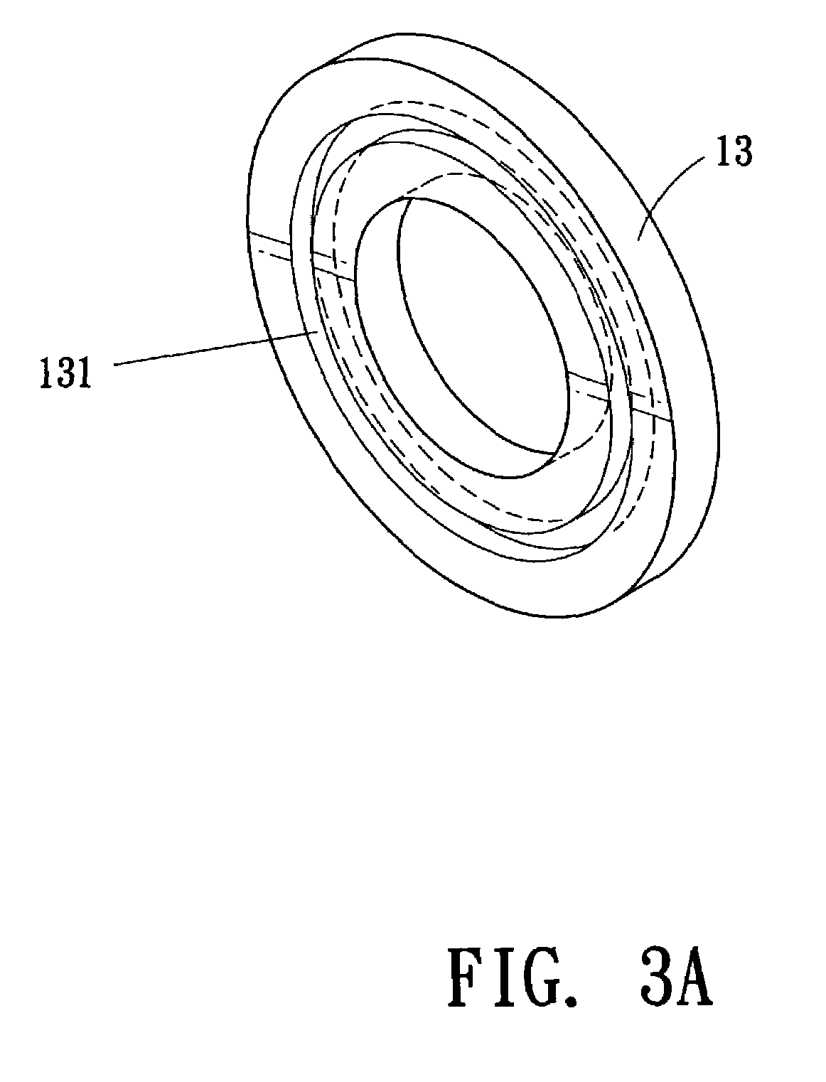
[0020]Referring to FIG. 2, a color wheel 1 provided by an embodiment of the invention includes a motor body 11, a housing 12, a spacer 13, and a color filter 14. The housing 12 is set to one side of the central axis of the motor body 11. The spacer 13 is placed over the housing 12. The color filter 14 is set on one side of the spacer 13, which is opposite the housing 12, so that there is a recess 15 between the color filter 14 and the housing 12.

[0021]In this embodiment, the motor body 11 mainly includes a shell, a magnetic ring (not shown), laminated steel stack (not shown) and a coil (not shown). When the coil is turned on, the laminated steel stack produces a magnetic force and a magnetic field. The positive or negative properties as well as the intensity of the current may cause the magnetic field to vary in an ordered manner. That is, a r...


PUM


Abstract

A color wheel including a motor body, a housing, a spacer and a color filter. In this case, the housing is set to a side of the central axis of the motor body. The spacer is placed over the housing. The color filter is set on one side of the spacer, which is opposite the housing, so that there is a recess between the color filter and the housing.

Description

BACKGROUND OF THE INVENTION[0001]1. Field of the Invention[0002]The invention relates to a color wheel and more particularly, this invention relates to a color wheel, which is used in the projection technology.[0003]2. Description of the Related Art[0004]Digital Light Processing (DLP) is a widely used projection technology. DLP has several advantages over other methods including high brightness, accurate tone reproduction, fast response time, noise-free operation, and thin and light composition.[0005]In a DLP projector, a digital control method and a reflection principle are adopted. Light rays from the light source are collected and focused by the lens to pass through three color filters. Then, the light rays are projected onto a digital micro-mirror device (DMD). Since the DMD includes several movable micro mirrors, driving electrodes may control the tilt angle and deflection time of each movable mirror. Then, the light rays are projected to form an image by switching the directio...

Claims


Application Information

Patent Timeline
Patent Type & Authority Patents(United States)
IPC IPC(8): G02B5/22G03B21/14H04N9/31
CPCG02B26/008H04N9/3114H04N9/3197
Inventor CHIN, KE-SHUCHANG, CHIH-NENGCHANG, KUANG-HUAKENG, YIN-TAIYU, AN-HWA
Owner TRANSAKT
Why Eureka
Try Eureka