
Articulated arm for awnings

a technology of articulation arms and awnings, applied in the direction of sunshades, construction, building construction, etc., can solve the problems of excessive wide articulation, anti-aesthetic effect, and accumulation of dirt, and achieve the effect of aesthetic appearan

Inactive Publication Date: 2008-11-18
LLAZA
View PDF14 Cites 23 Cited by
  • Summary
  • Abstract
  • Description
  • Claims
  • Application Information

AI Technical Summary

Benefits of technology

"The invention is an articulated arm with a unique articulation configuration between the arm and forearm. The arm has a flexible pulling element in the form of a flat belt that is pulled by a motor and is supported on the arm. The articulation configuration includes conical surfaces and low-friction materials to guide and support the forearm on the arm. The arm also has stops to limit its rotation angle. The articulation configuration provides a safer and more protected articulation with an improved appearance."

Problems solved by technology

This exposure of the chain or cable involves the risk of dirt accumulating in the articulation zone and moreover, produces an anti-aesthetic effect in a product that is destined to be permanently in view of the public.
One inconvenience of such a design is that the thick cables produce an excessively wide articulation and the mentioned top is another part which adds to the complexity to the articulation and increases its cost.

Method used


Image

  • Articulated arm for awnings
  • Articulated arm for awnings
  • Articulated arm for awnings

Examples


Embodiment Construction

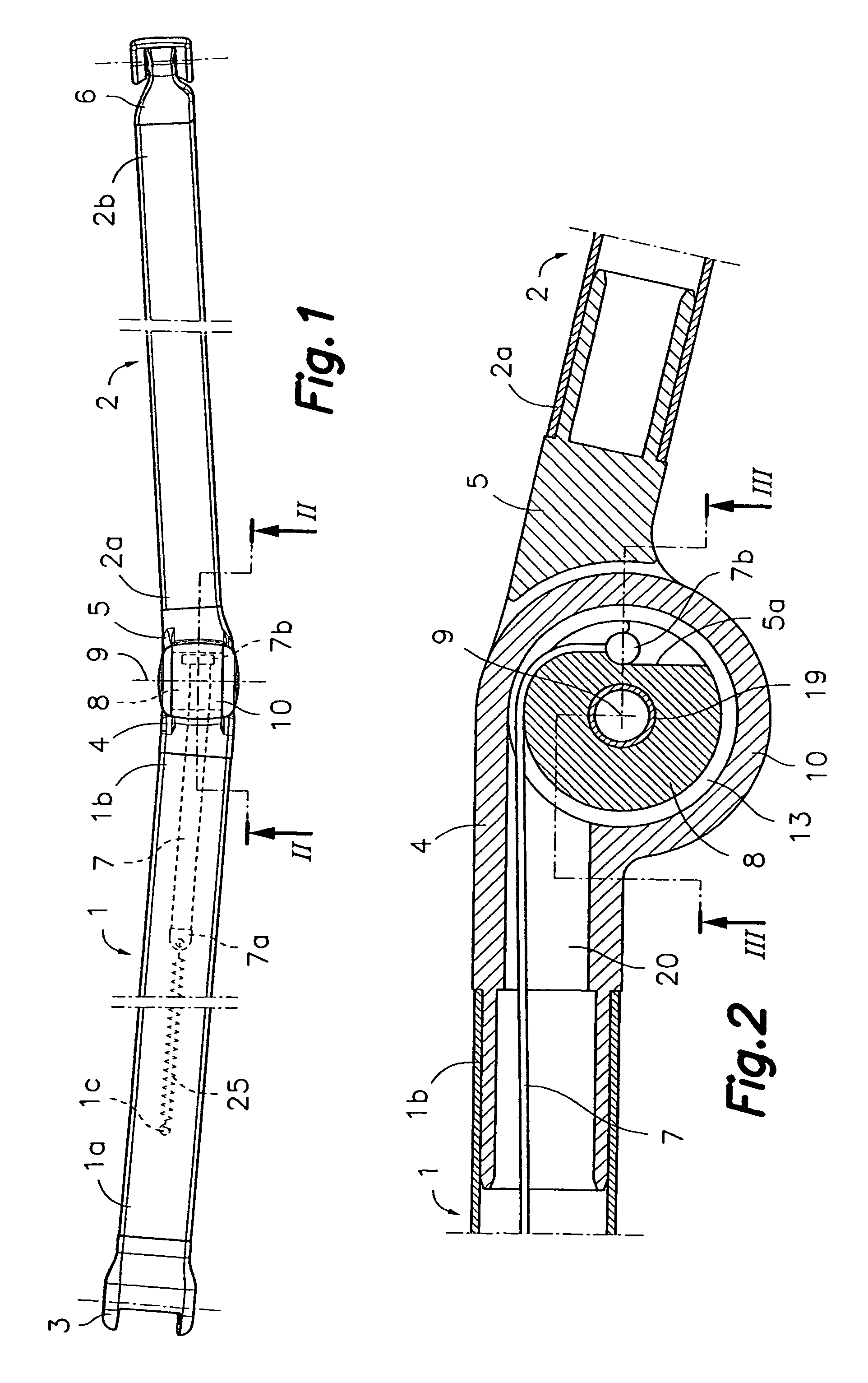
[0021]First referring to FIG. 1, the articulated arm for an awning in accordance with this invention comprises, as is usual, an arm 1, consisting of a tubular profile with first and second ends, 1a, 1b and a forearm 2, also consisting of the tubular profile with some first and second ends, 2a, 2b. The first end 1a of arm 1 is coupled to a part that defines a securing configuration 3 for the articulated joint to a fixed support (not shown). The second end 1b of arm 1 and the first end 2a of the forearm 2 are plugged into respective parts that define articulated configurations 4, 5 for a mutual articulated joint of arm 1 and forearm 2. Finally, the second end 2b of the forearm 2 is plugged into a part that defines a support configuration 6 for the articulated joint of forearm 2 to an awning load bar (not shown). Within a cavity inside arm 1, there is a flexible pulling element 7 (shown in broken lines) with a first end 7a linked to an elastic elements 25 secured to a fixed point 1c of...


PUM


Abstract

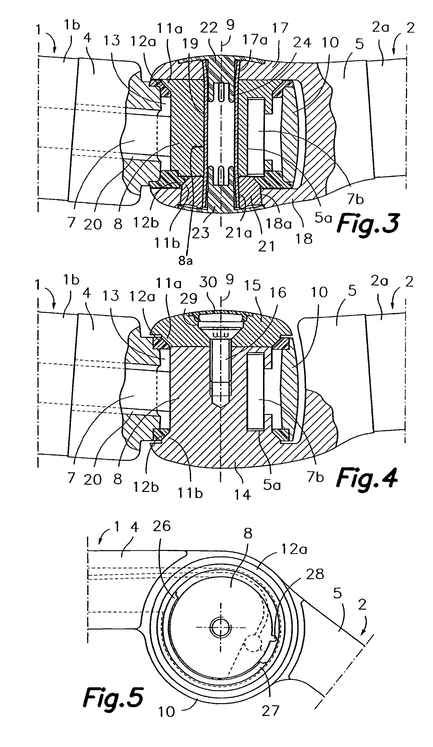
An articulated arm for awnings is disclosed. It comprises an arm and a forearm connected by an articulated joint by means of respective articulation configurations at adjacent ends. The articulation configuration at the end of the forearm comprising a core with an exterior surface around a shaft, and the articulation configuration at the end of the arm comprising a surrounding wall around the core. A bearing is incorporated between the core and said wall to guide a relative rotation between the two. There is a flexible pulling element inside the arm, with a first end linked to an elastic element secured to a fixed point on the arm and a second end secured in the core. This element passes through a connection in the configuration and is partially housed in a space between the core and the wall.

Description

[0001]This application is a U.S. National Phase Application of PCT International Application No. PCT / ES2003 / 000404, filed Aug. 1, 2003.SCOPE OF THE INVENTION[0002]This invention deals with an articulated arm for an awning that comprises an arm and a forearm that are mutually articulated by respective articulation configurations located at adjacent ends of the same, and pushed towards an open position by a flexible pulling elements that is linked to an elastic element housed inside the arm and linked to the cite articulation. The mentioned articulation configurations are designed so that the pulling element is completely out of sight and protected in any arm position.BACKGROUND TO THE INVENTION[0003]A general configuration is known for articulated arms for awnings that has become classic and according to which, the arm comprises an arm and forearm consisting of first and second tubular elements with parts at their ends connected to a plug defined by articulation configurations. The a...

Claims


Application Information

Patent Timeline
Patent Type & Authority Patents(United States)
IPC IPC(8): E04F10/06
CPCE04F10/0611E04F10/0618E04F10/0622E04F10/0651
Inventor LLAGOSTERA FORNS, JOAN
Owner LLAZA
Learn More