
Contaminant detector for food inspection

a technology for detecting food and contaminant, applied in the direction of material analysis, testing food, instruments, etc., can solve the problems of consuming a relatively large amount of power, affecting the quality of food inspection, so as to reduce production costs, reduce production costs, and produce with different aperture sizes and conveyor speeds

Inactive Publication Date: 2008-11-11
THERMO FISHER SCIENTIFIC INC
View PDF5 Cites 8 Cited by
  • Summary
  • Abstract
  • Description
  • Claims
  • Application Information

AI Technical Summary

Benefits of technology

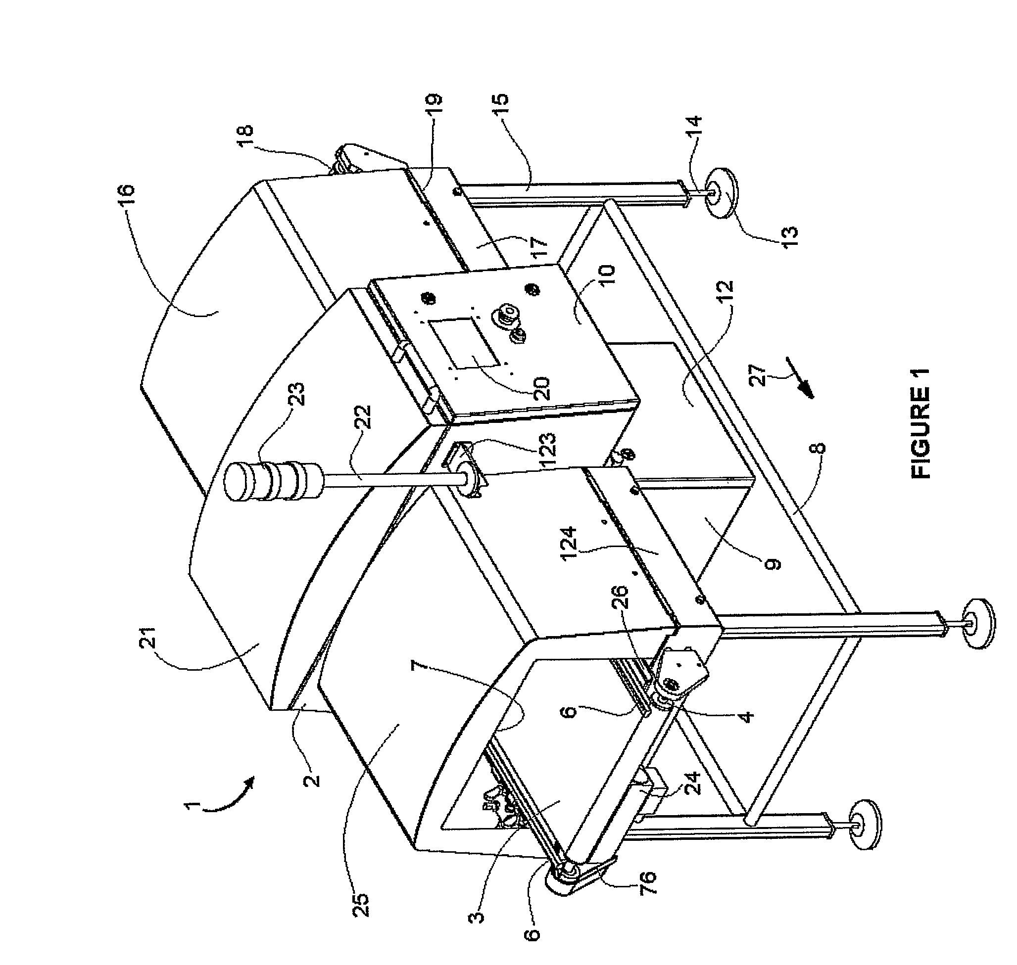
[0008]The present x-ray based contaminant detector addresses the disadvantages of prior art devices. In particular, the present invention is a contaminant detector for food inspection that utilizes lateral emission x-ray technology and which includes an integrated conveyor that passes the product under test near the x-ray emitting source. The machine is a conveyor line scan x-ray system that can be produced with different aperture sizes and conveyor speeds and at a relatively low cost. The present contaminant detector uses a wide-angle x-ray emitting source to generate the necessary x-ray radiation for penetrating the object under inspection, thereby permitting detection of a contaminant. Use of a wide transmission angle results in reduced production costs by eliminating the expense associated with a narrow angle radiation source.
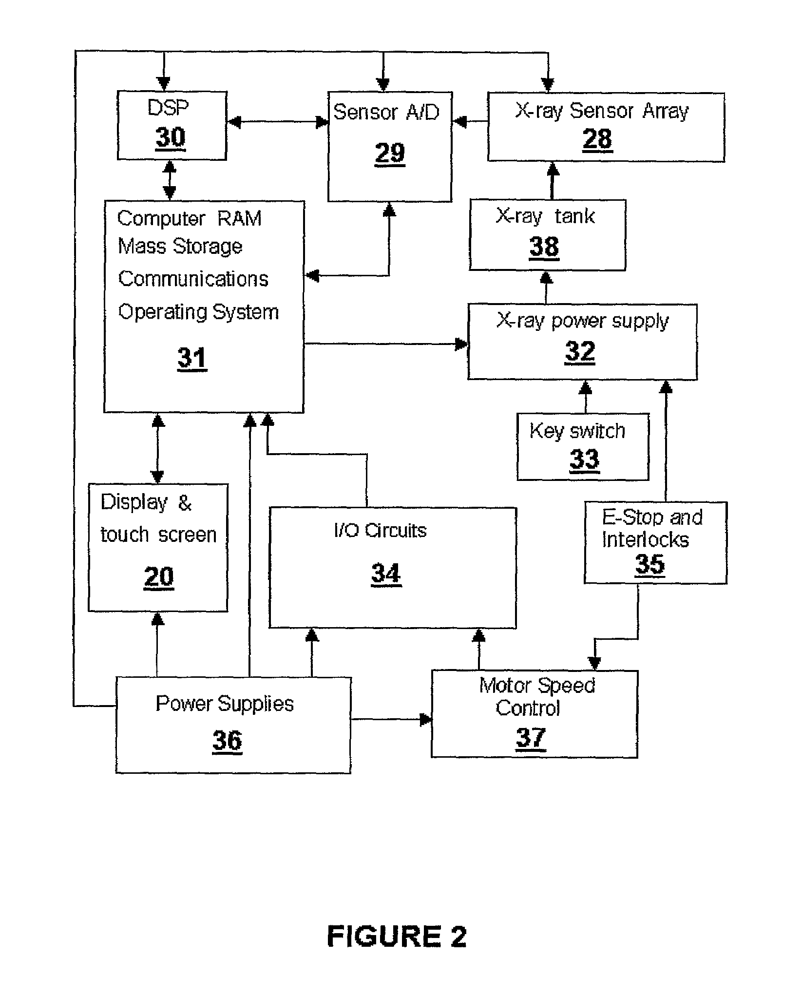
[0009]Product learning algorithms automatically determine nominal product characteristics and substantially reduce the need for operator assisted machine initialization activities. The operator typically needs only to pass a known nominal product through the machine in order to teach the machine the characteristics of an acceptable product. The controls are thus simplified in comparison to existing metal detectors, thereby eliminating or substantially reducing errors caused by the incorrect setup of operating parameters. The simpler design of the present contaminant detector produces a machine having relatively greater reliability and a longer life expectancy than other x-ray based food inspection machines
[0011]The present invention is intended primarily for metal detection applications where the type of contaminant, product, or the product packaging precludes the use of a conventional metal detector, such as, for example, when inspecting food residing in packages containing metal. Several advantages are offered by the characteristics inherent in the present invention. By using X-Rays for detection, there is no metal free zone restriction. For products that exhibit high and variable product effect with other metal detectors due to their conductivity, contaminant detection by x-ray provides the same sensitivity as is possible when detecting contaminants in a conventional, low conductivity product. The present invention permits a relatively lower cost per item inspected than a conventional x-ray based inspection machine. The cost per item is reduced by the use of a novel, relatively low power x-ray generation system and power supply, thereby reducing the cooling costs present in higher power x-ray inspection systems.
[0015]In the present invention the x-ray source and detector locations are altered when compared to existing x-ray based detection systems. The number of photons incident upon the x-ray detectors per unit area, known as the x-ray flux, decreases as the square of the distance from the x-ray source. By altering the positions of the source and detector, and thus having the x-ray source pointed generally upward, the OUI is closer to the source and it becomes possible to image products after the emitted x-rays have traveled a relatively smaller distance, thereby requiring significantly less x-ray generation for the same effective flux. This physical arrangement allows the use of an x-ray tube that is relatively smaller and which has lower power consumption, thus permitting the use of a less expensive cooling system.

Problems solved by technology

Conventional metal detectors often fail when detecting metal contaminants in products that incorporate metal as part of the product or the associated packaging.
However, if such a metal optimized setting is used, then the detection of bone or glass, as well as any relatively thin or small metal objects, is much less reliable.
A narrow angle x-ray source prevents radiation in unwanted directions and is necessary for safety reasons, but such a source consumes a relatively high amount of power and is relatively expensive.
This arrangement necessarily increases the cost of the resulting machine for several reasons.
First, an x-ray emitter requires a substantial power source which must be routed to the emitter location.
Second, the heat producing x-ray emitter is relatively difficult to cool in an enclosed, elevated location.
Fourth, the x-ray detectors reside beneath the conveyor where they are subject to additional contamination and are relatively difficult to cool, isolate from vibration and to service.
Additional problems encountered in a real world food processing assembly line process include the accumulation of contaminants on the test item conveying mechanism.
While the signal processing aspects of existing x-ray detection devices may be quite exotic, the cleanliness and serviceability or the conveyor belt is often primitive and results in downtime that renders the relatively high reliability of the electronics irrelevant to the total real world duty cycle of the machine.

Method used


Image

  • Contaminant detector for food inspection
  • Contaminant detector for food inspection
  • Contaminant detector for food inspection

Examples


Embodiment Construction

[0055]As seen in FIGS. 1 and 18, the contaminant detector 1 is a conveyor line scan x-ray inspection system designed primarily for contaminant detection in packaged products. The contaminant detector 1 provides a functional quality control system in a factory or product processing facility. The contaminant detector 1 is intended for use where conventional metal detectors fail, typically when detecting dense contaminants such as glass, bone, stone, and plastic or metal in products that incorporate metallic materials as a part of the product packaging. Examples of such products include metal foil encased foods, foods in aluminum tins, cans or trays, foods with metal foil freshness seals, and selected foods with thin metal lids, or items, such as lettuce, for example, or other foods without metal packaging but having high product effect with respect to conventional metal detectors.

[0056]The contaminant detector 1 includes an x-ray generation unit housing 9 which contains various intern...


PUM

PropertyMeasurementUnit
sizeaaaaaaaaaa
sizeaaaaaaaaaa
detection thresholdaaaaaaaaaa

Abstract

A contaminant detection machine (1) including a conveyor (3) which causes an object under inspection (79) to pass through a plane (48) of emitted x-ray radiation. The plane is generated by an x-ray tube (55) that emits a lateral beam, thereby permitting the distance (88) between the x-ray tube and the object under inspection to be reduced. A photo diode arch mounting assembly (104) is placed above the object under inspection and is mated to a collimator assembly (125) that also serves as the mounting bracket for the x-ray generation assembly (38), thereby preserving optical alignment between the photo diode detector array (28) and the emitted x-ray plane (48). The detector array (28) scans the object under inspection (79) so as to produce a continuous series of discrete lines, each line being analyzed by an image processing unit (116) to determine the presence or absence of a contaminant. The conveyor (3) passes over a pair of slider bed surfaces (155, 156) which are mounted in a hinged manner such that the leading edge (168) of one surface (156) is parallel to and spaced apart from the trailing edge (172) of the other surface (155), thereby creating a gap that is coplanar with the collimation slot (129) and the emitted x-ray plane (48). Each bed surface (155, 156) is rigidly constrained within open ended mounting brackets (159, 160, 161 and 162) yet can be removed by hand without the use of tools. Similarly, the conveyor (3) is supported by a roller assembly (182) that includes a tracking block (142) and pivot pin (143) which permits the roller assembly to be mounted to and removed from flip up mounts (151, 152) by hand and without the need of tools. Graphical user interfaces (249, 260, 261, 266, 275, 282 and 288) permit a user to operate the machine (1) by means of a liquid crystal display touch screen (20).

Description

[0001]This patent application claims priority based on U.S. Provisional Patent application Ser. No. 60 / 623,461, filed on Oct. 29, 2004.FIELD OF THE INVENTION[0002]The present invention relates generally to the field of detecting foreign material within an item undergoing inspection, and more particularly to a detecting apparatus that irradiates the inspected item with X-Rays.BACKGROUND OF THE INVENTION[0003]Conventional metal detectors often fail when detecting metal contaminants in products that incorporate metal as part of the product or the associated packaging. Examples of such products include foods encased in a metal foil, foods residing in aluminum cups, bowls or trays, foods with metal foil freshness seals, and foods fully or partially covered with thin metal lids. Other foreign materials such as bone, glass and stone may also be present in food items. X-rays have been used to irradiate food items in an attempt to detect foreign matter. An example of such a device is disclos...

Claims


Application Information

Patent Timeline
Patent Type & Authority Patents(United States)
IPC IPC(8): G01N23/04
CPCG01N23/06G01N33/02G01N2223/618G01N23/083
Inventor AINSWORTH, TERESABRO, YURIYCASH, FREDERICKDICKINSON, GARYEGGERTH, SCOTTERB, TOMFERGUSON, JEFFREYGESSNER, DAVIDHERBES, BRUCEJOHNSON, KEVINMOSKALENKO, SERGEYLOCKMAN, LORNASCHMIDT, DOUG
Owner THERMO FISHER SCIENTIFIC INC
Learn More