Zoom lens

a zoom lens and zoom technology, applied in the field of zoom lenses, can solve the problems of severe demand for miniaturization of the optical system, and the difficulty of reducing the size of the optical system required for telephoto use, and achieve the effect of small size and high performan

Active Publication Date: 2008-11-11
FUJI PHOTO OPTICAL CO LTD
View PDF12 Cites 3 Cited by
  • Summary
  • Abstract
  • Description
  • Claims
  • Application Information

AI Technical Summary

Benefits of technology

[0006]In view of the above, the invention provides a zoom lens small in size but high in performance that allows power variation on a relatively telephoto side.
[0008]In the zoom lens of this configuration, the power of the zoom lens varies by moving the second group along the optical axis with the first and third groups fixed. The fourth group is moved along the optical axis to perform correction of the position of the image plane and focusing, which is required due to the variation of the power. Particularly, since the first group is configured so that positive, positive and negative lenses are arranged in order from the object side, power arrangement in the first group is optimized, which is advantageous in reducing the size.
[0010]A combined refractive power of the second and third lenses of the first group may be negative. This configuration is advantageous in reducing the length of the lens. Also, the second and third lenses of the first group may form a cemented lens. This configuration can avoid the performance deterioration caused by assembling error. Also, in order to obtain a good optical performance in the visible region, at least one lens of the first group satisfies the following conditional expression (1). Furthermore, in order to achieve a good optical performance over from the visible region to near-infrared region, the following conditional expression (2) may be satisfied. It is noted that νd denotes an Abbe number at d-line having 587.6 nm in wavelength.νd>50   (1)νd>75   (2)
[0011]The second group may include, in order from the object side, a first lens of the second group having a negative refractive power, a second lens of the second group having a biconcave shape and a third lens of the second group having a positive refractive power. By providing the cemented lens, performance deterioration due to assembling error can be avoided. Also, the second group may further include a lens having a positive or negative refractive power on the object side of the first lens of the second group or on the image side of the third lens of the second group. This configuration is advantageous in reducing the aberration variation due to power variation. Furthermore, the third lens of the second group satisfies the following conditional expression (3). This configuration suppresses the movement amount of the second group, which is advantageous in reducing the size. It is noted that N23 denotes a refractive index of the third lens of the second group at d-line having 587.6 nm in wavelength.N23>1.75   (3)
[0012]The third group may include at least one lens having a positive refractive power and at least one lens having a negative refractive power. This configuration is advantageous in correcting the longitudinal chromatic aberration caused in the third group, thus making it possible to increase the aperture ratio. In this case, the third group may include, in order from the object side, a first single lens of the third group having a positive refractive power and a second single lens of the third group having a negative refractive power with a concave surface directed to the object side. This configuration is advantageous in size reduction and cost reduction. Alternatively, the third group may include a cemented lens formed of a first lens of the third group having a positive refractive power and a second lens of the third group having a negative refractive power with the first and second lenses of the third group arranged in order from the object side. This configuration is advantageous in the capability to avoid the performance deterioration due to assembling error. Also, the least one lens of the third group having the positive refractive power may have at least one aspheric surface. This configuration can increase the aperture ratio while maintaining the size reduction.
[0013]The fourth group may have a positive refractive power. Also, the fourth group may include, in order from the object side, a first lens of the fourth group having a negative refractive power with a concave surface directed to the object side, a second lens of the fourth group having a positive refractive power and a third lens of the fourth group having a positive refractive power. At least one surface of the lenses of the fourth group having the positive refractive power may be aspheric. This configuration is advantageous in correcting aberrations and can increase the aperture ratio. In this case, at least one surface of the third lens of the fourth group may be aspheric. Also, at least one lens of the fourth group satisfies the following conditional expression (4). This configuration can prevent the longitudinal chromatic aberration from increasing over the entire power variation range of from the wide-angle end to the telephoto end.νd>75   (4)

Problems solved by technology

Also, because of spread of a small dome camera, demand for miniaturization of the optical system also becomes severe.
However, it is difficult that such an optical system required for telephoto use is reduced in size so as to be received in the dome camera even if the zoom ratio is made small.

Method used


Image

  • Zoom lens
  • Zoom lens
  • Zoom lens

Examples


example

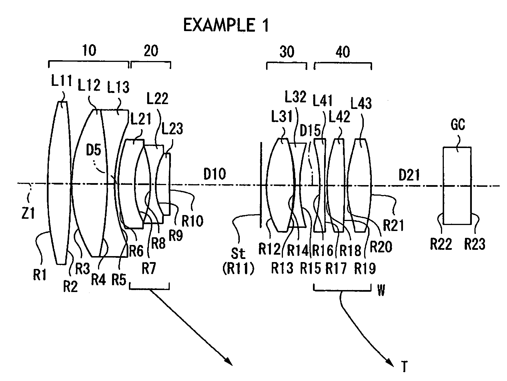
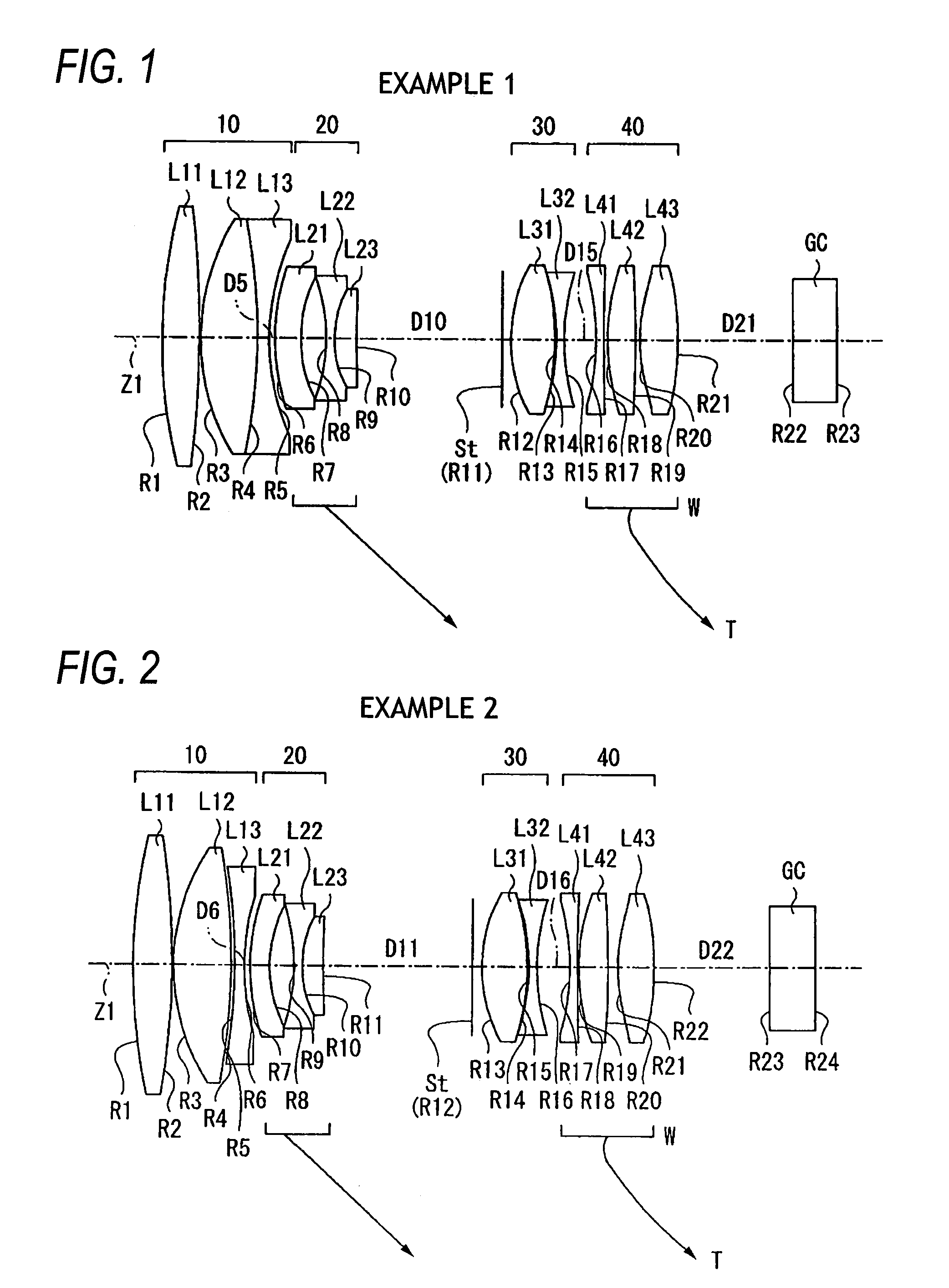
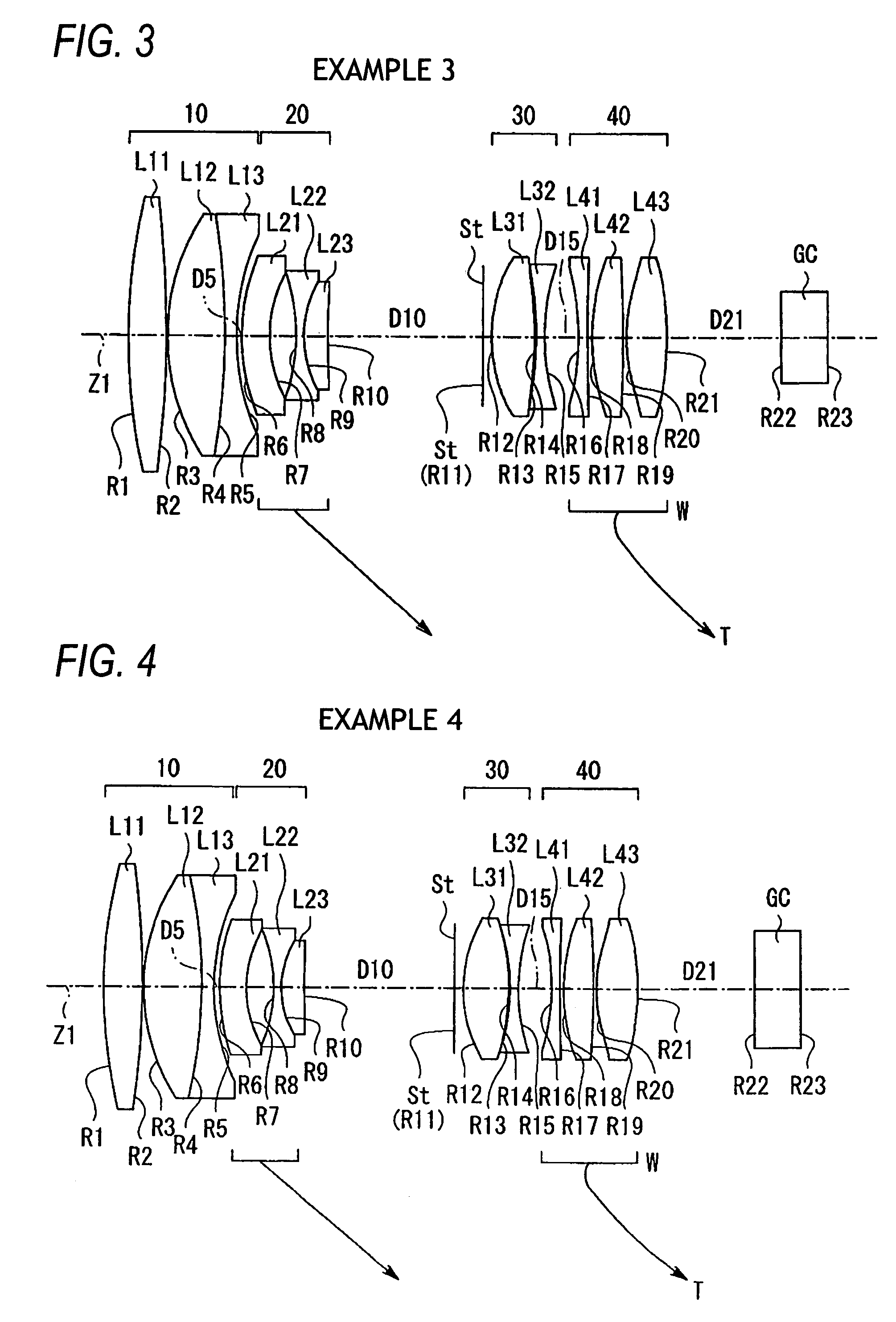
[0083]Specific numerical examples 1 to 8 of the zoom lens according to the embodiment will be collectively described based on the example 1.

[0084]FIGS. 9, 10(A) and 10(B) show, as an example 1, specific lens data corresponding to the lens configuration shown in FIG. 1. FIG. 9 shows the basic lens data, FIG. 10(A) shows data relating to aspheric surfaces, and FIG. 10(B) shows data which change along with zooming.

[0085]The column of surface number Si of FIG. 9 shows numbers of i-th (i=1 to 23) surfaces to which references are given with gradually increasing as approaching to the image side, and the surface of the constituent element closest to the object side is taken as a first surface. The column of curvature radius Ri shows values of curvature radius (mm) of each i-th surface as counted in order from the object side, correspondingly to the symbols Ri shown in FIG. 1. The column of distance between surfaces Di shows a distance (mm) on the optical axis between the i-th surface Si and...


PUM


Abstract

A zoom lens includes, in order from an object side, a first group having a positive refractive power, a second group having a negative refractive power, a diaphragm, a third group having a positive refractive and a fourth group following the third group. When a power of the zoom lens varies from a wide-angle end to a telephoto end, the second group is moved along an optical axis toward an image side with the first and third groups fixed to the optical axis so as to vary the power and the fourth group is moved along the optical axis to perform correction of a position of the image plane, which is associated with the variation of the power, and focusing.

Description

BACKGROUND OF THE INVENTION[0001]1. Technical Field[0002]The invention relates to a zoom lens having a zoom ratio of about 3.3 for use in a video camera, an electronic still camera or the like, and more particularly to a small-sized zoom lens that is used on a relatively telephoto side and suited for a dome monitoring camera or the like.[0003]2. Related Art[0004]There is known, as a zoom lens for use in a vide camera or a digital still camera, a zoom lens having a four group system in which the power of the zoom lens varies by moving a second group along the optical axis with first and third groups fixed and a position of an image plane is corrected by moving a fourth group. For example, JP 2006-3589 A (corresponding to US 2005 / 280901 A) and Japanese Patent No. 3391342 (corresponding to U.S. Pat. No. 6,404,561) have proposed the following zoom lens. An optical system includes a first group having a positive refractive power, a second group having a negative refractive power, a third...

Claims


Application Information

Patent Timeline
Patent Type & Authority Patents(United States)
IPC IPC(8): G02B15/14
CPCG02B15/173G02B15/144113
Inventor TOMIOKA, UKYO
Owner FUJI PHOTO OPTICAL CO LTD
Why Eureka
Try Eureka