
Wave powered system for generating energy

a technology of energy generation and wave power, applied in the direction of electric generator control, positive displacement liquid engine, machines/engines, etc., can solve the problems of device damage, designer overdesign of system, and no housing assembly

Inactive Publication Date: 2008-11-11
ANDALIA ROGER R
View PDF4 Cites 18 Cited by
  • Summary
  • Abstract
  • Description
  • Claims
  • Application Information

AI Technical Summary

Benefits of technology

[0009]It is another object of this invention to create a system that can store the energy generated for selective subsequent use.
[0011]It is yet another object of this invention to provide such a system that is inexpensive to manufacture and maintain while retaining its effectiveness.

Problems solved by technology

None of them, however, includes a housing assembly that protects the system that is cooperatively adapted to receive concentrated waves that are substantially contiguous over a predetermined range of waves.
However, if the devices are in resonance, the stress on the components will force the designer to overdesign the system to protect the former.
There have been many instances where the devices have been damaged.

Method used


Image

  • Wave powered system for generating energy
  • Wave powered system for generating energy
  • Wave powered system for generating energy

Examples


Embodiment Construction

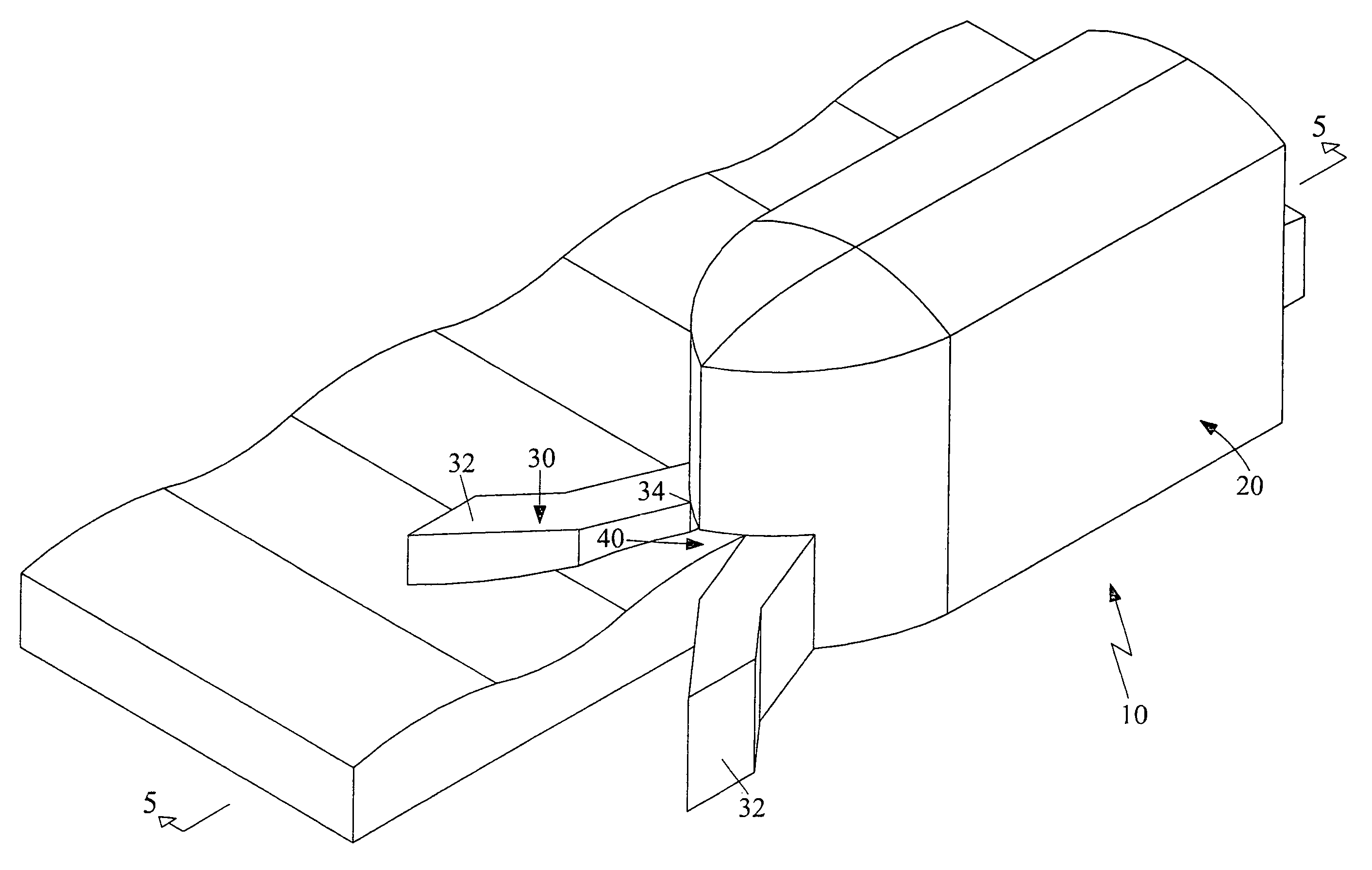
[0023]Referring now to the drawings, where the present invention is generally referred to with numeral 10, it can be observed that it basically includes housing structure 20, inlet portion 30, central channel 40, outlet portion 50, floater assemblies 60 positioned within channel 40.

[0024]Housing structure 20 is utilized and within which the different components are installed. Housing 20 includes an inlet 30 and outlet 50 with channel 40 in between. Inlet 30 has a wave concentrator or tapered channel with open end 32 that is constrained at point 34 where it meets central channel 40. Optionally, channel 40 is covered with longitudinally extending lateral walls 42; 44 and channel cover wall 46. Covering channel 40 is important to protect the mechanical equipment from corrosion. The height of inlet 30 at point 34 is such that protection is provided to the internal equipment from large waves that exceed a predetermined height. Inlet 30 thus provides the means for enhancing the waves rece...


PUM


Abstract

An apparatus powered by waves to generate hydraulic energy that includes a housing structure, an inlet portion, a central channel, an outlet portion and floater assemblies positioned within the channel. Within the housing structure the different components are installed. The inlet has an open end that is constrained at the point where it meets the central channel. Several floating assemblies are contiguously aligned and exposed to the movements caused by the waves running through the channel. The floaters include a hingedly mounted arm and a distal end. The arm is rotably mounted to a fixed point in the housing. The rotational movement is transmitted to a reciprocating piston of a hydraulic system that generates pressurized fluid fed to a hydraulic line. A number of hydraulic storage devices are provided to store the hydraulic energy. A manifold assembly is connected to these storage devices to provide the necessary energy for hydraulic turbine generators of electricity.

Description

BACKGROUND OF THE INVENTION[0001]1. Field of the Invention[0002]The present invention relates to a system powered by waves to generate energy, and more particularly, to generate hydraulic energy.[0003]2. Description of the Related Art[0004]Several designs for harnessing and generating energy from the ocean waves have been designed in the past. A summary of past developments has been documented in Misha Cornes' article Ocean Wave energy Conversion: The Next Wave in Renewable Energy?-http: / / www.bfi.org / Trimtab / summer01 / ocean. None of them, however, includes a housing assembly that protects the system that is cooperatively adapted to receive concentrated waves that are substantially contiguous over a predetermined range of waves. It is desirable to receive contiguous waves rather than sudden large waves for several reasons, including the optimization of the equipment design. The desirability of achieving this resonance between the waves and the system capturing their movement is docume...

Claims


Application Information

Patent Timeline
Patent Type & Authority Patents(United States)
IPC IPC(8): F03C1/00
CPCF03B13/141F03B13/1815F04B17/00F05B2260/406Y02E10/38Y02E10/30
Inventor ANDALIA, ROGER R.
Owner ANDALIA ROGER R
Learn More