
Fixed seat of a socket

a socket and fixed seat technology, applied in the field of socket structure, can solve the problems of socket falling off from the housing, poor structural stability of the ribs, and failure to connect to the power source and the imaging of the flat panel display

Inactive Publication Date: 2008-11-04
BENQ CORP
View PDF5 Cites 8 Cited by
  • Summary
  • Abstract
  • Description
  • Claims
  • Application Information

AI Technical Summary

Benefits of technology

[0014]The object of the present invention is to provide a fixed seat of the socket firmly holding the socket on the PCB so as to avoid the pulling force of the plug to crack the PCB.
[0015]The another object of the present invention is to provide a flat panel display having the fixed seat of the socket, and the fixed seat can avoid any movement between the socket and the PCB pulling out of the plug.

Problems solved by technology

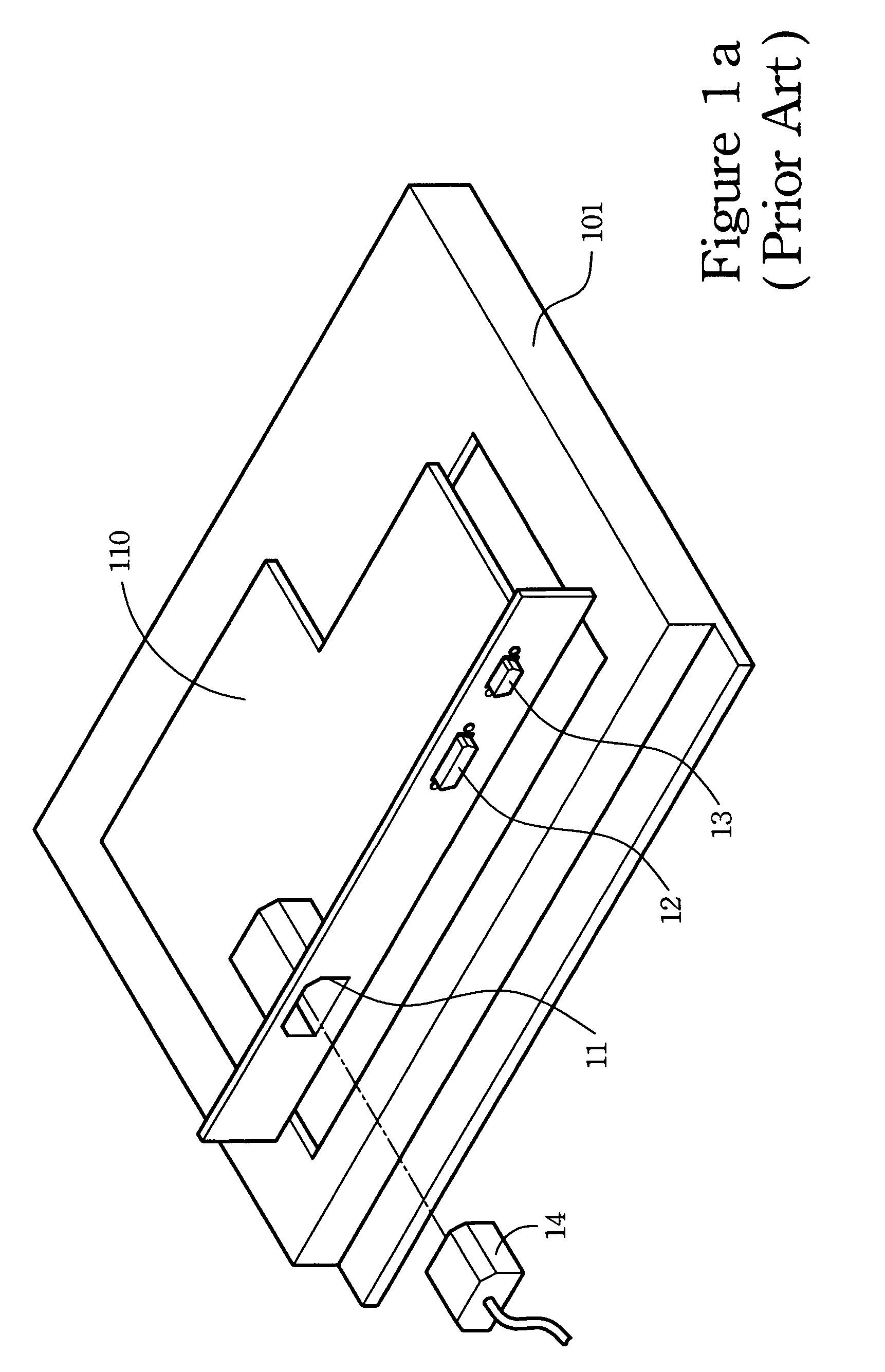
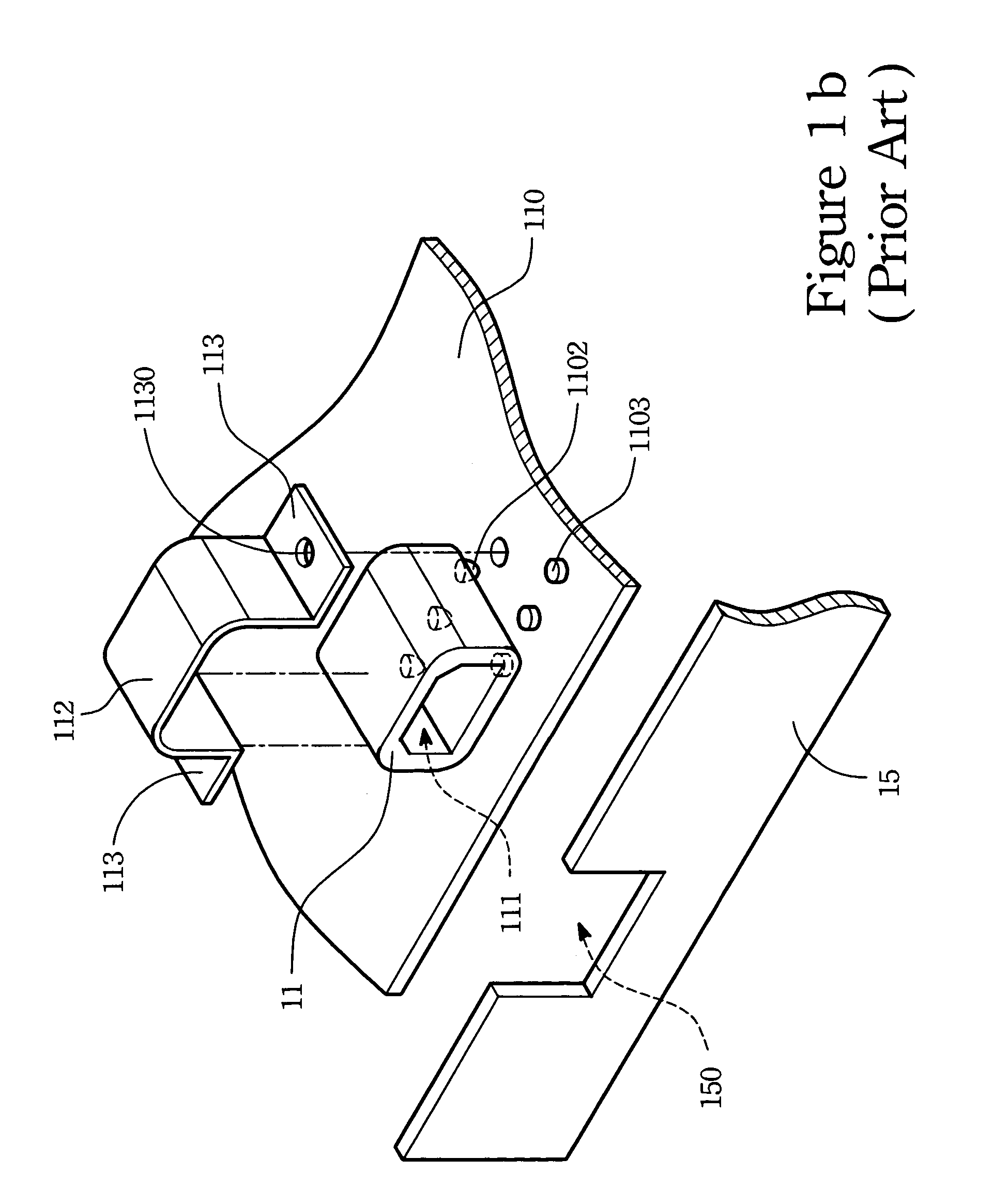
In some accidental situations, the pulling force may be large enough to crack the welding between the socket 11 and the PCB 110 that may finally lead to fail the connection to the power source and the imaging of the flat panel display.
In addition, with respect to the retrieval force through the plug, the direction arrangement of the ribs is not good for structural stability.
In particular, the socket may fall off from the housing after frequently usage.
Besides, when the plug is anchored inside the socket, the welding between the socket and the PCB needs to sustain the disturbance force from the plug.
So, any accidental force upon the socket or the plug may be easily to crack the welding between the socket and the PCB.
Definitely, any crack to the welding may interrupt the power source to the flat panel display.

Method used


Image

  • Fixed seat of a socket
  • Fixed seat of a socket
  • Fixed seat of a socket

Examples


Embodiment Construction

[0037]The object of the present invention is to provide a fixed seat of the socket for avoiding any relative movement of the socket with respect the side plate while the socket meets a pull-out or push-in of an external plug.

[0038]The fixed seat applicable to the flat panel display or other display device is set to a side plate of the corresponding display device so as to protect welds between the socket and the PCB from being cracked by applications upon the plug.

[0039]Referring now to FIG. 2, a flat panel display having a fixed seat of a socket in accordance with the present invention is shown. The flat panel display includes a panel display 301, a PCB 310 and other related elements. The PCB 310 is mounted to a back of the panel display 301, so as to drive the panel display 301. Also, to protect the PCB 310, a housing (not shown in the figure) for the PCB 310 can be included in the flat panel display.

[0040]A side plate 351 of the housing for the PCB 310 has a plurality of combinin...


PUM


Abstract

A socket having a flange is applied to a display device. The display device has a side plate further having a combining hole to mount the socket. When the socket is mounted inside the combining hole, the flange of the socket sticks the side plate around the combining hole and a clamp plate for clamping the side plate at the combining hole is placed on top of the socket. By providing the flange of the socket and the clamp plate, the socket can be firmly restricted at the combining hole.

Description

FIELD OF THE INVENTION[0001]The present invention relates to a socket structure, more particularly to the socket having a clamp plate to avoid possible cracks of the printed circuit board (PCB) caused by unexpected movement of the plug inside the socket.BACKGROUND OF THE INVENTION[0002]Recently, 3C products (communication, computer and consumer electronics) have already played important roles in daily life. In particular, the new emerging flat panel display that features less space occupation has quickly grasped people's attention and interests and is extending its market share over the traditional cathode ray tube displays.[0003]In the flat panel display industry, the liquid crystal display (LCD) is one of the well-developed products. The LCD has merits of lightweight, convenient moving and less space occupation and is widely applied to cell phones, language translators, digital cameras, PDAs and notebook computers.[0004]Referring to FIGS. 1a˜1c, a perspective back view of a conven...

Claims


Application Information

Patent Timeline
Patent Type & Authority Patents(United States)
IPC IPC(8): H01R13/73
CPCH01R13/748H01R12/716H01R12/724
Inventor TSUO, CHUN-JUNG
Owner BENQ CORP
Learn More