
Single-mode optical fiber

a single-mode optical fiber and optical fiber technology, applied in the field of single-mode optical fibers, can solve the problem of sudden increase in bending loss, and achieve the effect of small bending loss

Active Publication Date: 2008-10-21
THE FUJIKURA CABLE WORKS LTD
View PDF13 Cites 25 Cited by
  • Summary
  • Abstract
  • Description
  • Claims
  • Application Information

AI Technical Summary

Benefits of technology

The present invention provides an SMF with a very small bending loss while conforming to the characteristics of G.652. The SMF has a cut-off wavelength of 1260 nm or less, a zero-dispersion wavelength of 1300 nm to 1324 nm, an MFD at a wavelength of 1310 nm of 5.5 μm to 7.9 μm, and a bending loss that is 0.1 dB or less at a wavelength of 1550 nm. The SMF has a W-shaped refractive index profile with a relative refractive index difference of the central core and inner cladding of Δ1, and a relative refractive index difference of the inner cladding and outer cladding of Δ2, which satisfies the following conditions: 0.40%≦Δ1≦0.85% −0.20%≦Δ2≦0.00% −1.0%<Δ3<Δ2. In addition, the patent text describes an SMF with a cut-off wavelength of 1260 nm or less, a zero-dispersion wavelength of 1300 nm to 1324 nm, an MFD at a wavelength of 1310 nm of 5.5 μm to 7.9 μm, and a bending loss that is 0.1 dB or less at a wavelength of 1550 nm. The SMF has a W-shaped refractive index profile with a relative refractive index difference of the central core and inner cladding of Δ1, and a relative refractive index difference of the inner cladding and outer cladding of Δ2, which satisfies the following conditions: 0.42%≦Δ1<0.85% −0.20<Δ2<0.00% −1.0%<Δ3<0.

Problems solved by technology

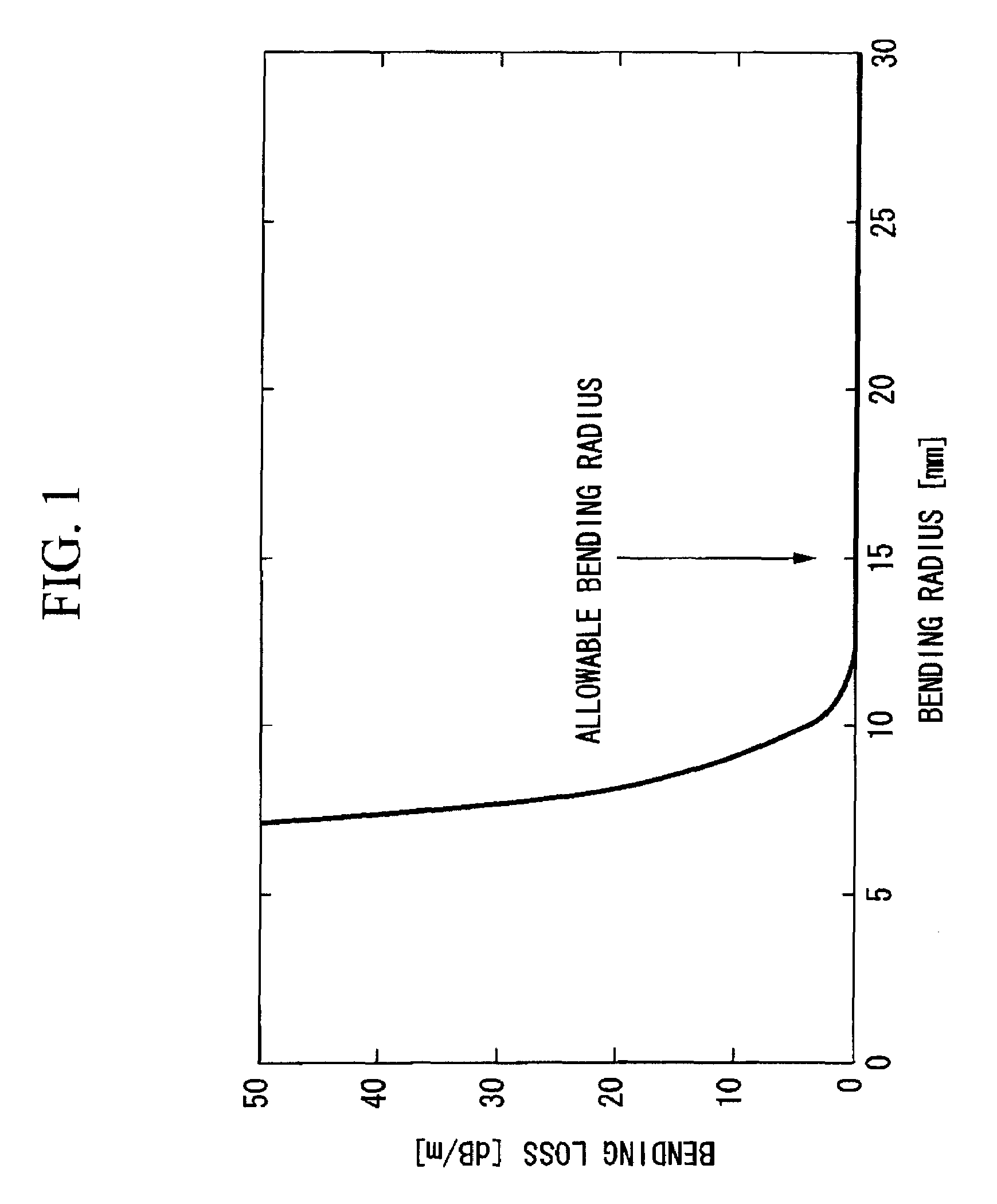
However, such optical fibers have a problem in that the bending loss suddenly increases with a bending radius of 15 mm or less. FIG. 1 is a graph exemplifying a bending radius dependence of the bending loss of an optical fiber with an allowable bending radius of 15 mm.
However, the chromatic dispersion on this level has rarely posed a problem over a distance on the order of several tens of meters, such as in indoor wiring.
However, there are cases where the chromatic dispersion value of the low bending loss optical fiber shown in Patent Document 1 poses a problem when the fiber is used in the PON system.
Therefore, there are cases where a large-absolute-valued chromatic dispersion value that the related art low bending loss fibers have is not preferable, because it may cause a communication failure.

Method used


Image

  • Single-mode optical fiber
  • Single-mode optical fiber
  • Single-mode optical fiber

Examples


example 1

[0082]In this example, the low bending loss SMF according to the present invention was manufactured based on Example 14 shown in Table 2. FIG. 3 shows the refractive index profile of the low bending loss SMF 10 manufactured in this example. This low bending loss SMF 10 was manufactured by first layering the central core 1 made of silica-based glass, the inner cladding 2, the trench portion 3, and a part of the outer cladding 4 by the Modified Chemical Vapor Deposition (MCVD) method, then performing an outside vapor deposition to layer the remaining outer cladding 5, and finally drawing the obtained optical fiber preform in the same manner as in the normal SMF. The characteristics of the obtained low bending loss SMF 10 were measured. The results are shown in Table 7.

[0083]

TABLE 7ItemMeasurement ResultTransmission Loss (at 1310 nm)0.360dB / kmTransmission Loss (at 1550 nm)0.208dB / kmCable Cut-off Wavelength1.21μmMFD (at 1310 nm)7.40μmMFD (at 1550 nm)8.21μmZero-Dispersion Wavelength1316....

example 2

[0085]In this example, the low bending loss SMF according to the present invention was manufactured based on Example 6 shown in Table 1. FIG. 4 shows the refractive index profile of the low bending loss SMF 20 manufactured in this example. This low bending loss SMF 20 was manufactured by first layering the central core 1 made of silica-based glass, the inner cladding 2, the trench portion 3, and a part of the outer cladding 4 by the MCVD method, then performing an outside vapor deposition to layer the remaining outer cladding 5, and finally drawing the obtained optical fiber preform in the same manner as in the normal SMF. The characteristics of the obtained low bending loss SMF 20 were measured. The results are shown in Table 8.

[0086]

TABLE 8ItemMeasurement ResultTransmission Loss (at 1310 nm)0.365dB / kmTransmission Loss (at 1550 nm)0.212dB / kmCable Cut-off Wavelength1.23μmMFD (at 1310 nm)6.19μmMFD (at 1550 nm)6.78μmZero-Dispersion Wavelength1306.2nmZero-Dispersion Slope0.086ps / nm2 / km...

example 3

[0089]In the example, the low bending loss SMF according to the present invention was manufactured based on Example 6 shown in Table 1. FIG. 5 shows the refractive index profile of the low bending loss SMF 30 manufactured in this example. This low bending loss SMF 30 was manufactured by first layering the central core 1 made of silica-based glass, the inner cladding 2, the trench portion 3, and a part of the outer cladding 4 by the MCVD method, then performing an outside vapor deposition to layer the remaining outer cladding 5, and finally drawing the obtained optical fiber preform in the same manner as in the normal SMF. The characteristics of the obtained low bending loss SMF 30 were measured. The results are shown in Table 9.

[0090]

TABLE 9ItemMeasurement ResultTransmission Loss (at 1310 nm)0.358dB / kmTransmission Loss (at 1550 nm)0.205dB / kmCable Cut-off Wavelength1.25μmMFD (at 1310 nm)7.67μmMFD (at 1550 nm)8.47μmZero-Dispersion Wavelength1309.3nmZero-Dispersion Slope0.088ps / nm2 / kmC...


PUM


Abstract

A single-mode optical fiber has a cut-off wavelength of 1260 nm or less, a zero-dispersion wavelength in the range of 1300 nm to 1324 nm, a zero-dispersion slope of 0.093 ps / nm2 / km or less, a mode field diameter at a wavelength of 1310 nm in the range of 5.5 μm to 7.9 μm, and a bending loss of 0.5 dB or less at a wavelength of 1550 nm, the bending loss being produced when the fiber is wound around a 10-mm radius for 10 turns.

Description

CROSS-REFERENCE TO RELATED APPLICATIONS[0001]This is a Continuation Application of International Application No. PCT / JP2005 / 015293, filed on Aug. 23, 2005, which claims priority to Japanese Patent Application No. 2004-250039, filed on Aug. 30, 2004, and Japanese Patent Application No. 2004-296369, filed on Oct. 8, 2004, the contents of which are entirely incorporated herein by reference.TECHNICAL FIELD[0002]The present invention relates to a single-mode optical fiber (hereinafter, referred to as an SMF) that has chromatic dispersion characteristics equivalent to those of a related art SMF and that has a very small bending loss when bent around a small radius.BACKGROUND ART[0003]Developments of a transmission system and an optical fiber that use Wavelength Division Multiplexing (WDM) have been actively advanced with the objective of increasing the data transmission rate in backbone and / or long-distance systems. Characteristics such as suppression of the nonlinear and control of the c...

Claims


Application Information

Patent Timeline
Patent Type & Authority Patents(United States)
IPC IPC(8): G02B6/02
CPCG02B6/02266G02B6/03644G02B6/0365G02B6/03672G02B6/03688G02B6/02223G02B6/02242G02B6/03611G02B6/028G02B6/036
Inventor MATSUO, SHOICHIROKUTAMI, HIROSHIHIMENO, KUNIHARUSAWANO, HIROYUKI
Owner THE FUJIKURA CABLE WORKS LTD
Learn More