
Wavelength selective switch

a selective switch and wavelength technology, applied in multiplex communication, instruments, optical elements, etc., can solve the problems of increasing module size, wasting resources, and wasting resources, and achieves the effects of small size, good accuracy, and simple construction

Inactive Publication Date: 2008-10-21
FUJITSU LTD
View PDF15 Cites 39 Cited by
  • Summary
  • Abstract
  • Description
  • Claims
  • Application Information

AI Technical Summary

Benefits of technology

This design enables accurate monitoring of wavelength channel power at each output port, reducing module size and cost while maintaining high accuracy, even with changes in MEMS mirror drive characteristics, and allows for optimal wavelength channel selection and guidance to target ports.

Problems solved by technology

In the connections between the above-described core networks and Metropolitan Area Networks that users access directly, there are concerns about the occurrence of bandwidth bottle necks due to limitations in electrical switching capability.
Hence, a lot of effort is being put into research and development to realize this.
Therefore, there are problems in that the module size is increased due to the increase in the number of optical parts, and in that the cost increases.
However, in this construction, since any influence such as a shift in the optical axis of the optical parts after passing through the optical branching device is not contained in the optical power monitored by the PD array, there is a possibility that the power of the light physically guided to each output port, and the monitored power in the PD array do not match.

Method used


Image

  • Wavelength selective switch
  • Wavelength selective switch
  • Wavelength selective switch

Examples


Embodiment Construction

[0037]Hereunder is a description of the best mode for carrying out the present invention, with reference to the appended drawings. Identical reference numerals denote identical or equivalent parts throughout all of the drawings.

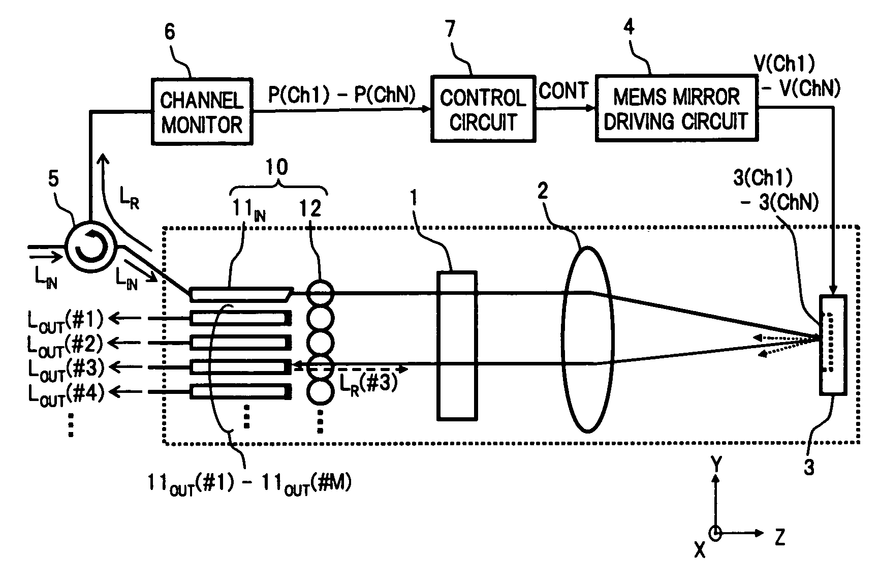
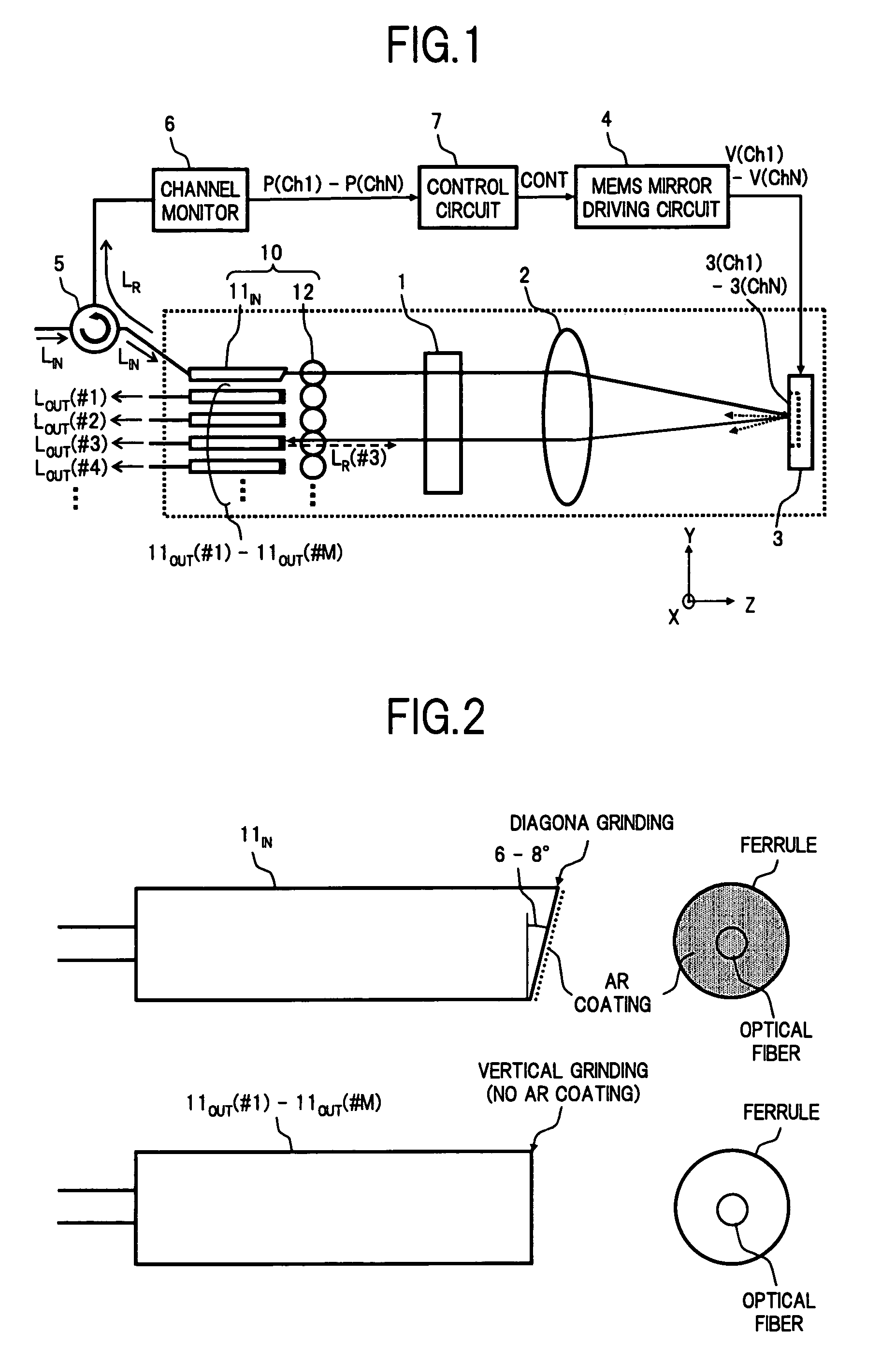
[0038]FIG. 1 is a diagram showing the structure of an embodiment of a wavelength selective switch according to the present invention.

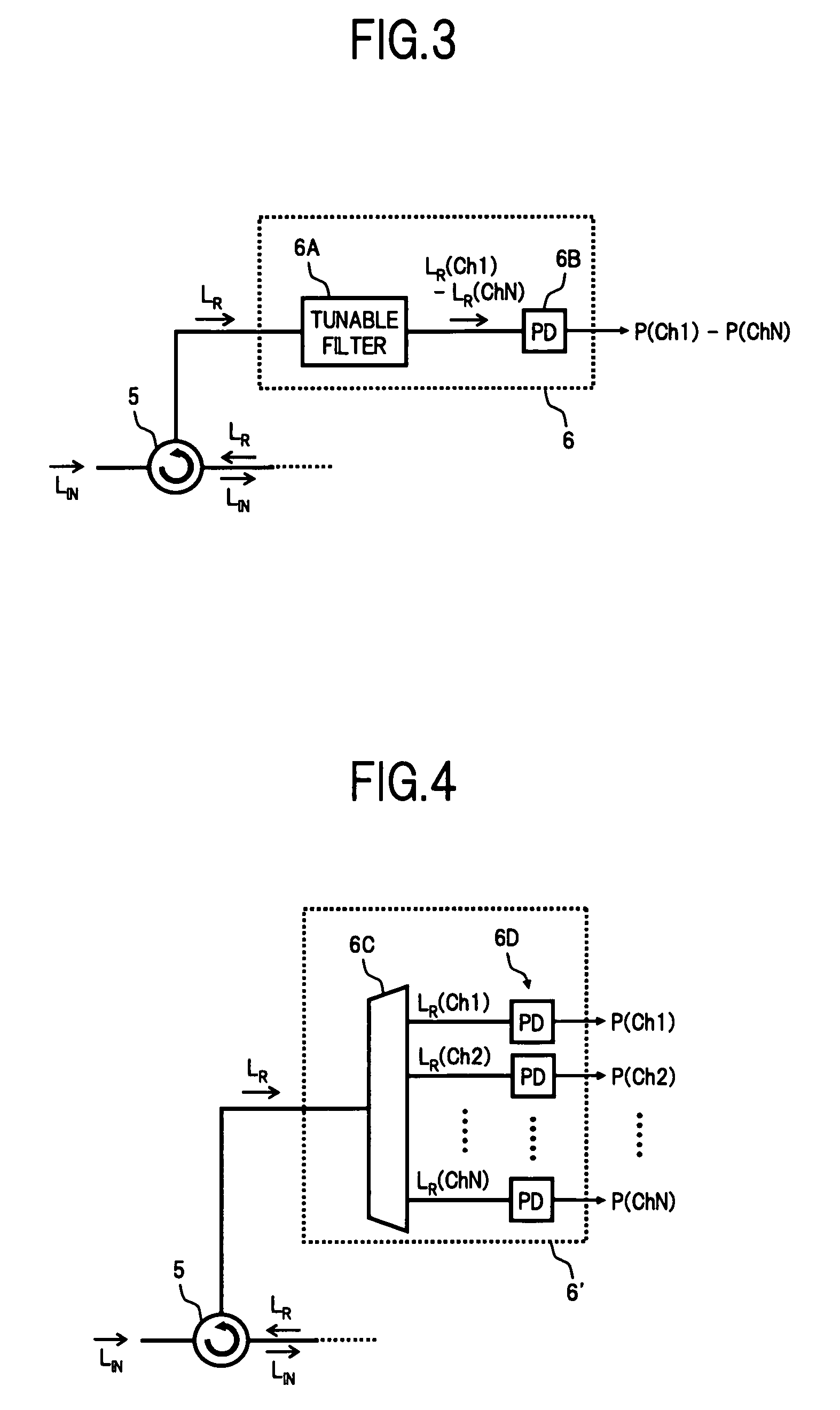
[0039]In FIG. 1, the wavelength selective switch of the present embodiment comprises for example: a fiber collimator array 10 serving as an optical input / output section; a diffraction grating 1 serving as a spectroscopic section; a condenser lens 2; a mirror array 3 in which a MEMS mirror, which is a plurality of movable mirrors, is arranged; an MEMS mirror drive circuit 4 serving as a movable mirror driving section; an optical circulator 5 serving as a reflected light extracting section; a channel monitor 6 serving as a reflected light monitor section; and a control circuit 7 serving as a control unit. The three-dimensional str...


PUM


Abstract

A wavelength selective switch of the invention separates WDM light coming out from an input fiber of a fiber collimator array according to its wavelength, in a diffraction grating, and reflects each wavelength channel proceeding in different directions by MEMS mirrors corresponding to a mirror array. In the MEMS mirrors, the angles of their reflecting surfaces are set corresponding to the location of the output port which is set in the output address of the wavelength channel to be injected. For each of the wavelength channels that reach the target output port, one part of each is reflected by the end face of an output fiber, and the reflected light is returned to the input port, and sent to a channel monitor via an optical circulator, so that the optical power corresponding to each wavelength channel is monitored. As a result it is possible to provide a small size, and low-cost, wavelength selective switch, that can monitor the power of each wavelength channel guided to a plurality of output ports, with good accuracy.

Description

BACKGROUND OF THE INVENTION[0001](1) Field of the Invention[0002]The present invention relates to a wavelength selective switch that can select a desired wavelength channel from a wavelength division multiplexed (WDM) light applied to an input port, and output it to a target output port. In particular, it relates to a wavelength selective switch that has a function for monitoring the optical power output from a plurality of output ports.[0003](2) Description of Related Art[0004]The recent rapid spread of high speed access networks that have bandwidths of approximately several Mbit / s to 100 Mbit / s, such as FTTH (Fiber to The Home), ADSL (Asymmetric Digital Subscriber Line), and the like, has created an environment in which broad bandwidth internet services can be received. In order to deal with the increase in communication demand under such conditions, mass storage optical communication systems in which wavelength division multiplexing (WDM) techniques are used, are being built into...

Claims


Application Information

Patent Timeline
Patent Type & Authority Patents(United States)
IPC IPC(8): G02B6/26G02B26/08H04B10/07H04B10/27H04B10/40H04B10/50H04B10/60H04J14/00H04J14/02
CPCH04Q11/0005H04Q2011/003H04Q2011/0032
Inventor OIKAWA, YOICHIAKIMOTO, KAZUAKI
Owner FUJITSU LTD
Learn More