Method for measuring dissociation rate coefficient by surface plasmon resonance analysis

a surface plasmon and dissociation rate technology, applied in the direction of instruments, color/spectral property measurements, material analysis, etc., can solve the problems of increased labor, deterioration of measurement accuracy, cost-consuming and time-consuming,

Inactive Publication Date: 2008-10-21
FUJIFILM CORP +1
View PDF11 Cites 1 Cited by
  • Summary
  • Abstract
  • Description
  • Claims
  • Application Information

AI Technical Summary

Problems solved by technology

However, since conventional methods require complicated operations or labeling substances, several techniques are used that are capable of detecting the change in the binding amount of a test substance with high sensitivity without using such labeling substances.
(a) performing a measurement wherein analyte concentrations are set at different levels (FIG. 4);
(b) measuring the amount of ligands immobilized in advance and calculating the Rmax value based on the measured value (FIG. 5); and
(c) performing nonlinear regression analysis by employing Rmax as a variable as with Ka and Kd. However, it is cost-consuming and time-consuming to carry out the measurement (a) due to an increased number of measurement operations. The measurement (b) was also problematic in terms of a prolonged measurement time, an increased amount of labor, and deterioration in measurement accuracy due to errors resulting from variations in the amount of ligands immobilized. When nonlinear regression analysis is performed as in the case of the (c) above, detection accuracy was also deteriorated due to errors resulting from increased computational effort and errors resulting from variations in the amount of ligands immobilized.

Method used


Image

  • Method for measuring dissociation rate coefficient by surface plasmon resonance analysis
  • Method for measuring dissociation rate coefficient by surface plasmon resonance analysis
  • Method for measuring dissociation rate coefficient by surface plasmon resonance analysis

Examples


examples

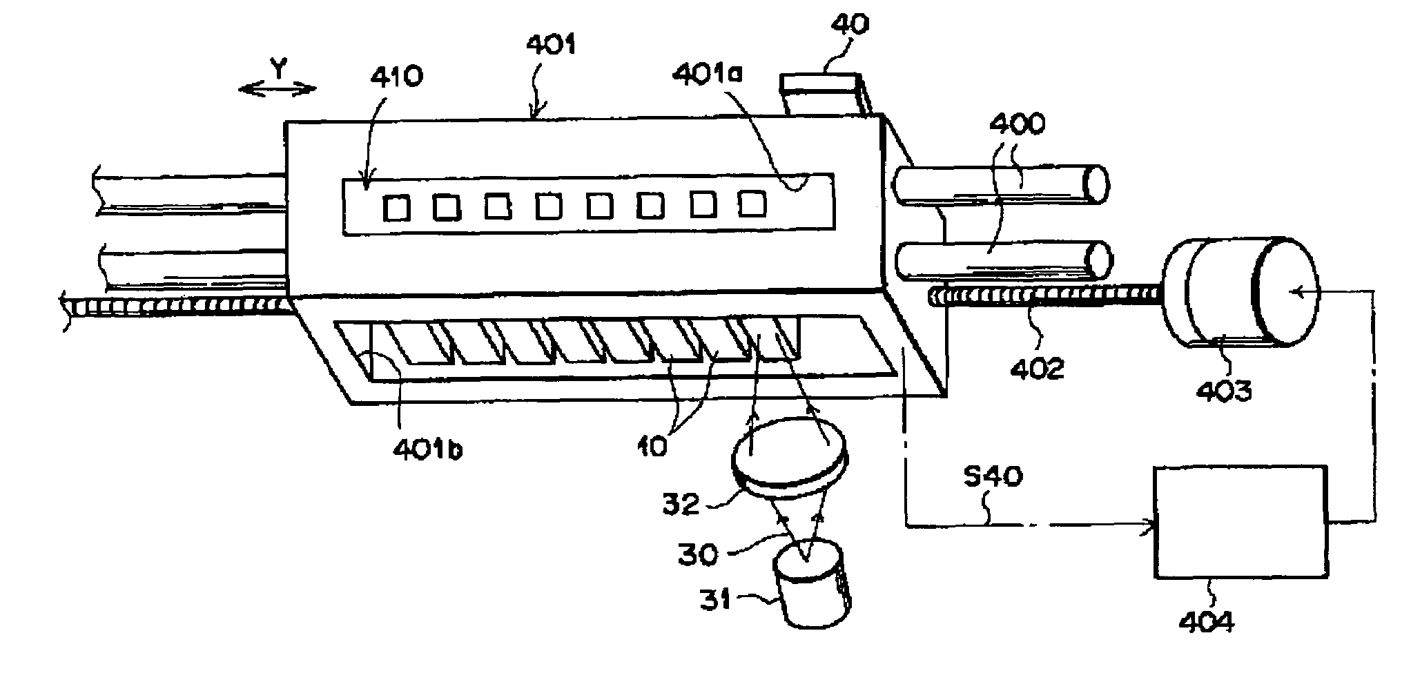
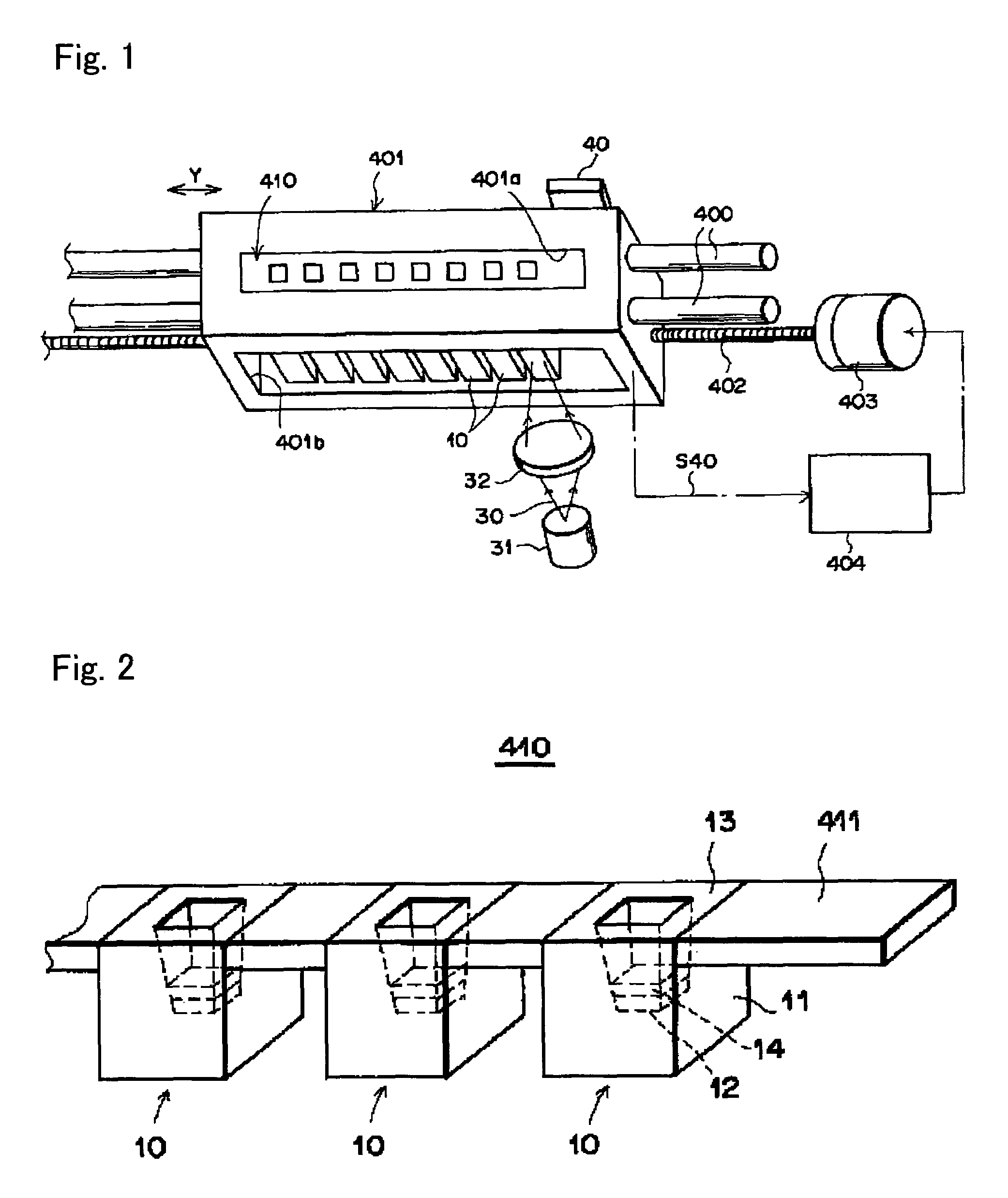
[0092]The following experiment was carried out using a device shown in FIG. 22 of Japanese Patent Laid-Open No. 2001-330560 (hereinafter referred to as the surface plasmon resonance measurement device of the present invention) (shown in FIG. 1 of the present specification) and a dielectric block shown in FIG. 23 of Japanese Patent Laid-Open No. 2001-330560 (hereinafter referred to as the dielectric block of the present invention) (shown in FIG. 2 of the present specification).

[0093]In the surface plasmon resonance measurement device shown in FIG. 1, a slide block 401 is used as a supporting medium for supporting measurement units, which is joined to two guide rods 400, 400 placed in parallel with each other while flexibly sliding in contact, and which also flexibly moves linearly along the two rods in the direction of an arrow Y in the figure. The slide block 401 is screwed together with a precision screw 402 placed in parallel with the above guide rods 400, 400, and the precision s...


PUM

PropertyMeasurementUnit
timeaaaaaaaaaa
timeaaaaaaaaaa
timeaaaaaaaaaa

Abstract

An object of the present invention is to provide a method for measuring the dissociation rate coefficient (Kd) by surface plasmon resonance analysis without measuring the theoretical maximum amount of binding (Rmax). The present invention provides a method for measuring the dissociation rate coefficient (Kd) of the reaction between an analyte molecule immobilized on a metal surface and a molecule that interacts with the analyte molecule by assaying changes in surface plasmon resonance signals using a surface plasmon resonance measurement device, wherein the signal and the slope of the dissociation curve of the surface plasmon resonance signal curves, or the signal ratio are used to calculate the dissociation rate coefficient (Kd).

Description

TECHNICAL FIELD[0001]The present invention relates to a method for measuring the dissociation rate coefficient of the reaction between an analyte molecule immobilized on a metal surface and a molecule that interacts with the analyte molecule by surface plasmon resonance analysis.BACKGROUND ART[0002]Recently, a large number of measurements using intermolecular interactions such as immune responses are being carried out in clinical tests, etc. However, since conventional methods require complicated operations or labeling substances, several techniques are used that are capable of detecting the change in the binding amount of a test substance with high sensitivity without using such labeling substances. Examples of such a technique may include a surface plasmon resonance (SPR) measurement technique, a quartz crystal microbalance (QCM) measurement technique, and a measurement technique of using functional surfaces ranging from gold colloid particles to ultra-fine particles. The SPR meas...

Claims


Application Information

Patent Timeline
Patent Type & Authority Patents(United States)
IPC IPC(8): G01N33/557G01N33/553G01N21/05G01N21/27G01N21/41G01N21/75
CPCG01N21/553G01N33/542G01N33/54373G01N21/272Y10S436/805
Inventor OHTSUKA, HISASHIOGURA, NOBUHIKO
Owner FUJIFILM CORP
Why Eureka
Try Eureka