
Nanoparticle coatings for flexible and/or drawable substrates

a technology of flexible and/or drawable substrates and nanoparticles, which is applied in the direction of synthetic resin layered products, transportation and packaging, ceramic layered products, etc., can solve the problems of appearance and performance problems, negative effects of nanoparticles on the function and appearance of the coating, and large surface area of nanoparticles, so as to minimize surface distortion, improve the effect of withstandability and high gloss

Active Publication Date: 2008-10-21
PPG IND OHIO INC
View PDF38 Cites 66 Cited by
  • Summary
  • Abstract
  • Description
  • Claims
  • Application Information

AI Technical Summary

Benefits of technology

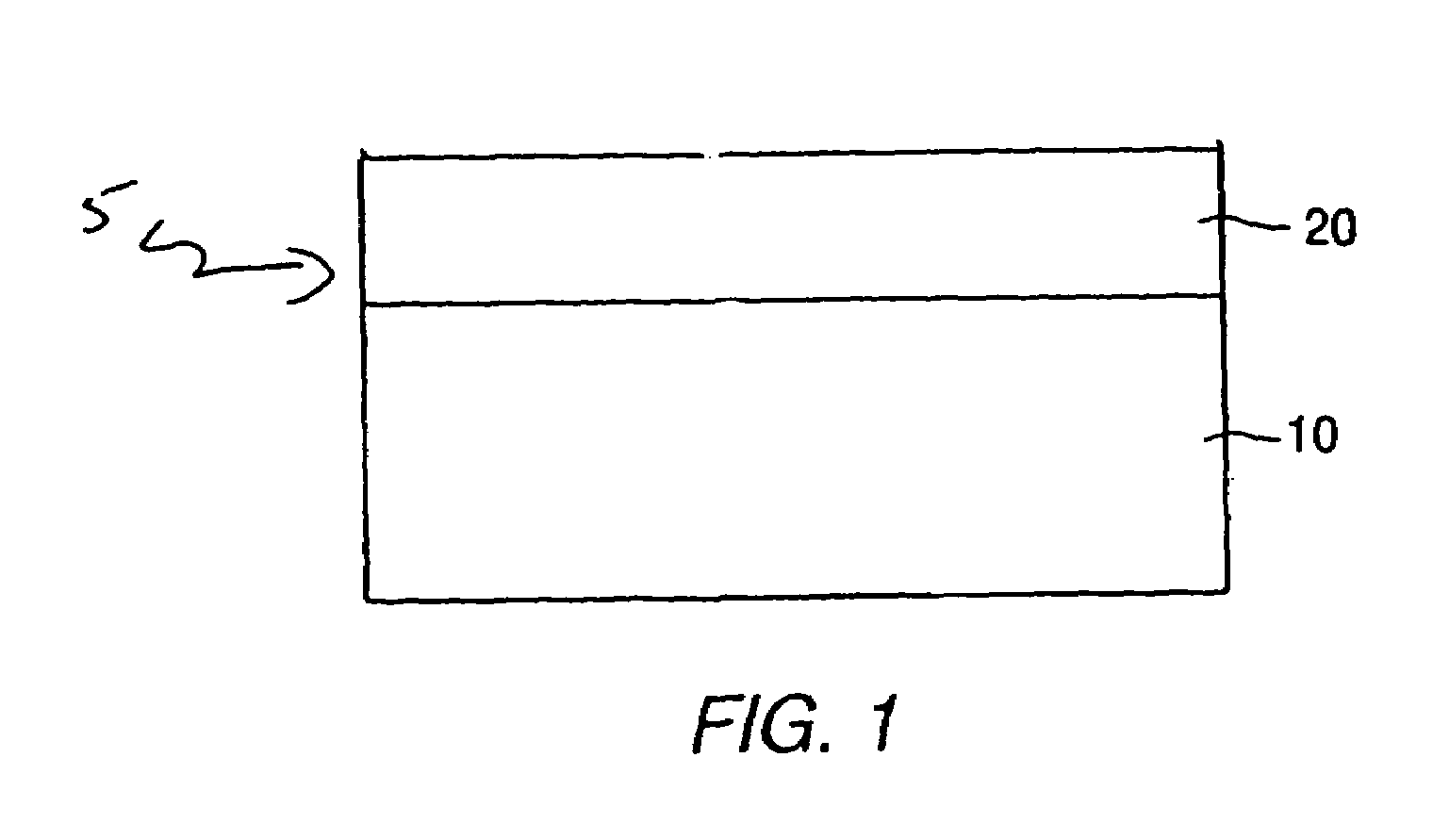
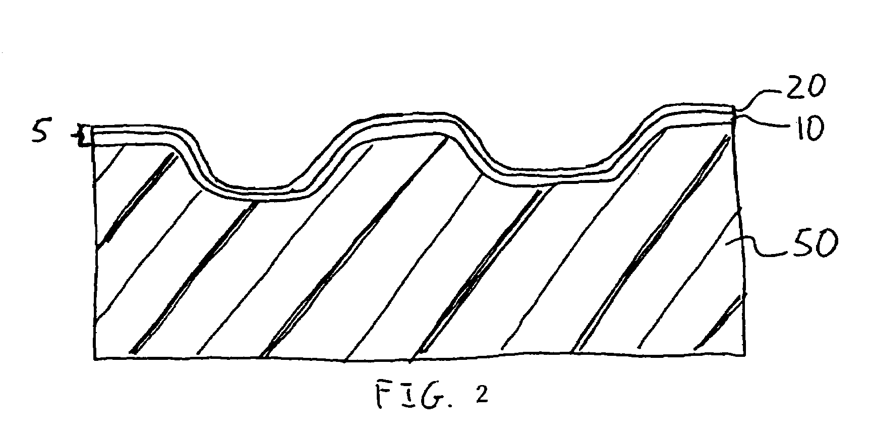
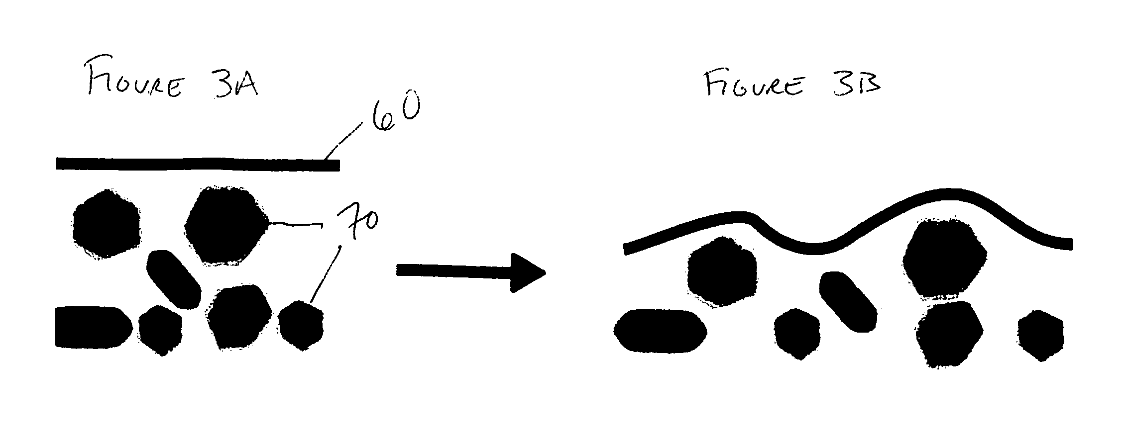
[0003]The present invention provides flexible and / or drawable substrates at least a portion of which is coated with a coating comprising a dispersion of resin-coated nanoparticles. Methods for making and using such substrates are also within the scope of the present invention. A particular use for the coated flexible and / or drawable substrates is in the area of manufacturing laminated articles. The present coated flexible and / or drawable substrates are typically durable and are capable of withstanding substantial elongation before breaking. Because nanoparticles are used, thinner coatings can be applied to the flexible and / or drawable substrates; the thinner coatings are better able to withstand the stresses to which the flexible and / or drawable substrates are subjected, such as those that occur during the lamination and / or molding process. In addition to being particularly suitable for flexible and / or drawable substrates, the present coatings provide desirable visual characteristics including high gloss. This can eliminate the need for a subsequent clear coat layer as desired in certain applications. Although not wishing to be bound by any mechanism, this is believed to result from the minimized surface distortion obtained when using the particles of the present invention; smooth mold surfaces in molding and laminate procedures are also believed to contribute to enhanced gloss in certain embodiments.

Problems solved by technology

Nanoparticles have a relatively large surface area, however, and will therefore often agglomerate in a coating.
While this agglomeration can be avoided to some extent by the use of grind vehicles, dispersants, and the like, the presence of these components in the coating can have negative effects on the function and appearance of the coating.
There is a particular need for such coatings for application to flexible and / or drawable substrates; upon distortion, elongation, and the like that such substrates undergo, micron-sized particles or agglomerated nanoparticles can often distort the coating surface causing both appearance and performance issues.

Method used


Image

  • Nanoparticle coatings for flexible and/or drawable substrates
  • Nanoparticle coatings for flexible and/or drawable substrates
  • Nanoparticle coatings for flexible and/or drawable substrates

Examples


example 1

Polyurethane / Urea Prepolymer

[0074]This example describes the preparation of a polyurethane / urea prepolymer that was subsequently used to form the aqueous composite microparticles of Example 6. The polyurethane / urea prepolymer was prepared from a batch of the following mixture of ingredients in the ratios indicated:

[0075]

IngredientsEquivalentsWeight (grams)Charge IN-methyl pyrrolidinone269.8Hydroxyethyl methacrylate (HEMA)0.7091.1Dimethylolpropionic acid (DMPA)3.50234.7Triphenyl phosphite2.2Dibutyltin dilaurate2.2Butylated hydroxytoluene2.2Charge IIPoly (butylene oxide)11.40700.0Charge IIIMethylene bis(4-cyclohexylisocyanate)8.401100.4Charge IVButyl methacrylate481.8Charge VButyl acrylate642.5Charge VIDeionized water4263.3Dimethylethanolamine1.40124.7Diethanolamine0.7073.6Ethylenediamine1.4042.11Poly (butylene oxide) having a number average molecular weight of 1000.

[0076]Charge I was stirred in the flask at a temperature of 100° C. until all solids were dissolved. Charge II was added...

example 2

Polyurethane / Urea Prepolymer

[0077]This example describes the preparation of a polyurethane / urea prepolymer which was subsequently used to form the aqueous composite microparticles of Example 7. The polyurethane / urea was prepared from a batch of the following mixture of ingredients in the ratios indicated:

[0078]

IngredientsEquivalentsWeight (grams)Charge IN-methyl pyrrolidinone232.7Hydroxyethyl methacrylate1.0130.1Dimethylolpropionic acid4.0268.3Triphenyl phosphite2.6Dibutyltin dilaurate2.6Butylated hydroxytoluene2.6Charge IIPoly (butylene oxide)22.01000.0Charge III4,4′-methylenebis(cyclohexyl isocyanate)8.01048.0Charge IVButyl acrylate200.0Charge VDiethanolamine1.0105.1Charge VIMethyl methacrylate930.6Butyl acrylate730.62Poly (butylene oxide) having a number average molecular weight of 1000.

[0079]The polyurethane / urea was prepared in a four-neck round bottom flask equipped with an electronic temperature probe, mechanical stirrer, condenser, and a heating mantle. Charge I was stirred ...

example 3

Acrylic Dispersant

[0080]This example describes the preparation of an acrylic dispersant which was subsequently used to form the aqueous composite microparticles of Example 4. The acrylic dispersant was prepared from a batch of the following mixture of ingredients in the ratios indicated:

[0081]

IngredientsWeight (grams)Charge IMAGNESOL320.0Toluene120.0Charge II2,2′-dipyridyl7.5Copper (0) powder6.1Charge IIIPara-toluenesulfonyl chloride30.4Charge IVBenzylmethacrylate169.2Glycidyl isopropyl ether20.0Charge VMPEG (550) MA4888.3Toluene250.03MAGNESOL POLYSORB 30 / 40, a synthetic magnesium silicate available from The Dallas Group of America.4BISOMER MPEG 550MA, a methoxypolyethylene glycol methacrylate available from Laporte Specialty Organics.

[0082]Charge I was mixed in a 2 liter flask with air-stirrer, thermocouple and azeotropic distillation set-up. Charge I was heated to reflux and water was azeotroped off. Charge I was then cooled and put under a nitrogen blanket.

[0083]Charges II and II...


PUM

PropertyMeasurementUnit
thicknessaaaaaaaaaa
elongationaaaaaaaaaa
wt %aaaaaaaaaa

Abstract

Flexible and / or drawable substrates having coatings comprising a dispersion of resin coated nanoparticles are disclosed, as are laminated articles comprising such flexible and / or drawable substrates.

Description

FIELD OF THE INVENTION[0001]The present invention relates to coated flexible and / or drawable substrates, and more particularly to flexible and / or drawable substrates having coatings with a dispersion of resin-coated nanoparticles.BACKGROUND INFORMATION[0002]Nanoparticles can be used for many purposes in coatings. For example, “hard” nanoparticles can be included in coatings to impart mar and / or scratch resistance, and pigment nanoparticles can be used in coatings to impart color. Nanoparticles have a relatively large surface area, however, and will therefore often agglomerate in a coating. While this agglomeration can be avoided to some extent by the use of grind vehicles, dispersants, and the like, the presence of these components in the coating can have negative effects on the function and appearance of the coating. Accordingly, there is a need for coatings having nanoparticulate dispersions in which these drawbacks are minimized if not avoided. There is a particular need for such...

Claims


Application Information

Patent Timeline
Patent Type & Authority Patents(United States)
IPC IPC(8): B32B5/16B32B18/00B32B27/00B32B27/36B32B3/26B32B5/18B32B27/20B32B27/40C08J7/043C08J7/046C09C1/30C09C3/10C09D7/41C09D7/62
CPCB32B5/18C08J7/047C09C1/3072C09D7/007C09D7/1225C09C3/10C08K3/0033C08K9/08Y10T428/265Y10T428/25Y10T428/259Y10T428/252C09D7/41C09D7/62C08K3/013Y10T428/31663Y10T428/249978Y10T428/31855Y10T428/31721Y10T428/31551Y10T428/31725Y10T428/31507Y10T428/31786Y10T428/249953C08J7/0427C08J7/043C08J7/046C01P2004/64B32B37/12B32B7/12B32B3/26B32B2255/26B32B2266/025
Inventor FALER, DENNIS L.KULFAN, ANTHONY D.TRETTEL, VICTORIA A.
Owner PPG IND OHIO INC
Learn More