Running gear for rail vehicles

a running gear and rail vehicle technology, applied in the direction of bogies, railway components, transportation and packaging, etc., can solve the problems of unfavorable high transverse acceleration, achieve the effect of enhancing comfort, enhancing comfort, and adapting to existing running gears

Inactive Publication Date: 2008-10-21
BOMBARDIER TRANSPORTATION GMBH
View PDF10 Cites 4 Cited by
  • Summary
  • Abstract
  • Description
  • Claims
  • Application Information

AI Technical Summary

Benefits of technology

[0009]It is the object of the invention to eliminate the disadvantages of the prior art which have been described and, in particular, to propose a running gear for rail vehicles which allows higher speeds in curves. It is further the object of the invention to enhance comfort and to allow able adaptability of existing running gears.
[0011]One advantage of the solution according to the invention is that, by inclining the car body, the passenger does not experience any greater transverse acceleration despite higher speed. This results in enhanced comfort. In the solution according to the invention, the centrifugal force brings about the inclination of the car body. Thus, only small adjusting forces are required to adjust the inclination to the optimum extent. A further advantage is that existing running gears can be adapted at little expense.

Problems solved by technology

A disadvantage here is that, already at relatively low speed in the curve, an unfavourably high transverse acceleration occurs.
Furthermore, the rolling pole located under the vehicle floor results in large transverse movements at the level of the rows of seats which is generally perceived as unpleasant by passengers, as well as the need for a severely restricted clearance profile of the car body.

Method used


Image

  • Running gear for rail vehicles
  • Running gear for rail vehicles

Examples


Embodiment Construction

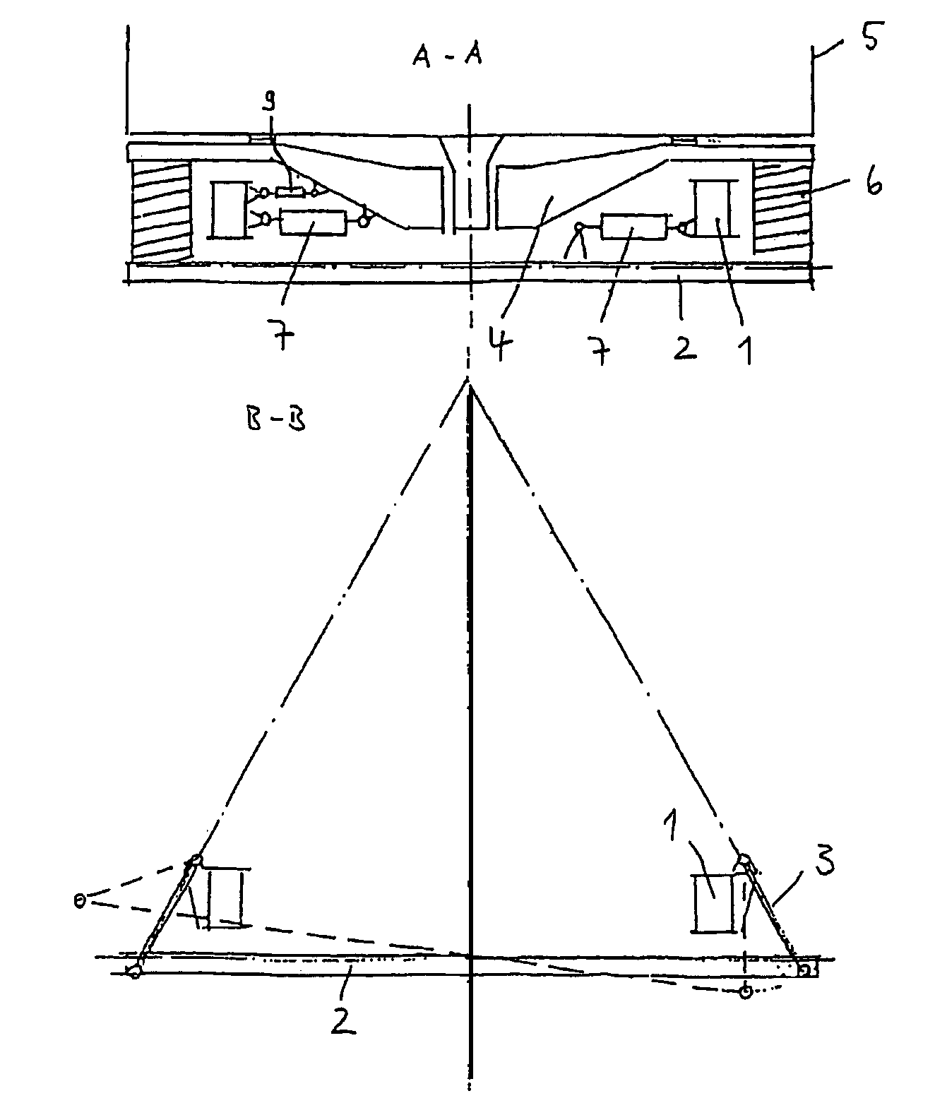
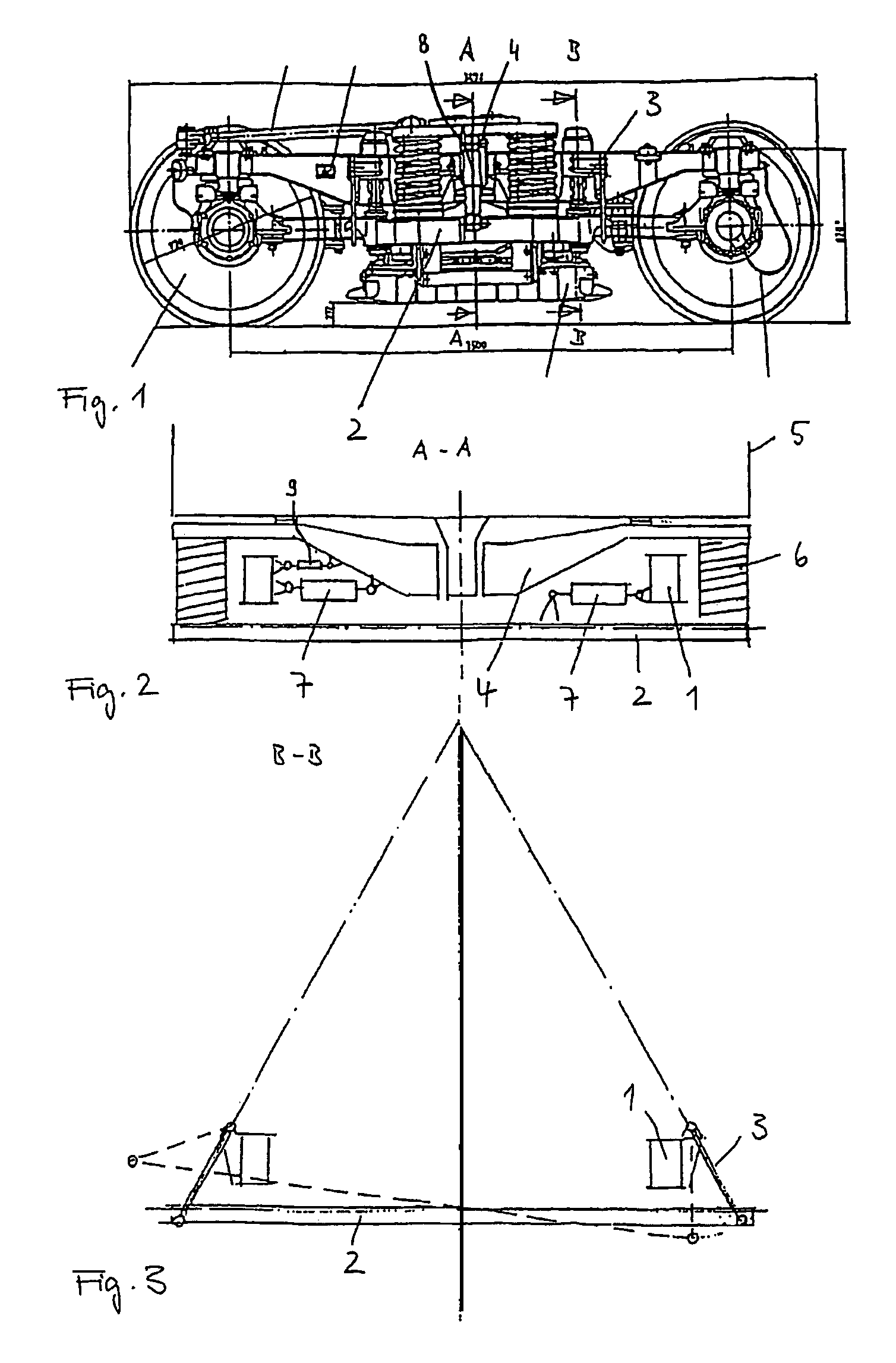
[0021]The FIGS. 1 to 3 show a running gear of a rail vehicle in different views. The running gear comprises a frame 1 which is supported via primary springs on wheels set. A spring carrier 2 is affixed on the running gear frame 1 by means of pendulums 3. The spring carrier 2 supports a rocker 4 with a car body 5 positioned thereon by means of secondary helical springs 6. The rocker 4 or the car body 5 is connected to the running gear frame 1 by means of shock absorbers damping vertical or rolling movements.

[0022]In a rail curve, the centrifugal force brings about a transverse displacement of the car body 5, the rocker 4 and, via the transverse rigidity of the secondary helical springs 6, also of the spring carrier 2.

[0023]An increase in the speed of travel in a curve results in an increase in the transverse acceleration acting on a passenger. However, this should not exceed a limit of, for example, 1.2 m / s2. So that this limit is not exceeded despite increasing the speed of travel, ...


PUM


Abstract

The invention relates to a running gear for rail vehicles, especially for passenger traffic, wherein a frame (1) is supported, by means of primary springs, on wheels or sets of wheels, and whereon a superstructure (5) is supported, optionally with insertion of a bolster (4). The bolster (4) or the superstructure (5) is supported by means of secondary springs, in relation to the frame (1), on at least one spring carrier (2), the bolster (4) or the superstructure (5) is connected to the frame (1) by means of a shock absorber used to damp vertical and / or rolling movements, and the spring carrier (2) is suspended on the frame by means of pendulums (3). The fixing points of the pendulums (3) on the running gear frame (1) are inwardly staggered, unlike vertically arranged pendulums, in such a way that the longitudinal axes of the pendulums (3) extend diagonally. At least one active control element (7) is at least partially arranged in the horizontal direction between the frame (1) and the spring carrier (2) or between the fame (1) and the bolster (4), in such a way that it supports the effect of the centrifugal force and adjusts the incline to an optimum value.

Description

BACKGROUND OF THE INVENTION[0001]1. Field of the Invention[0002]The present invention relates to a running gear for rail vehicles. The invention is suitable for, but not restricted to, use in rail vehicles for passenger traffic.[0003]2. Description of the Related Art[0004]EP 0 621 165 B1 describes a running gear for rail vehicles in which a running gear frame is carried via primary springs by the wheels or wheel sets and on which, via secondary springs, the car body of the rail vehicle is supported car via a rocker or directly. The rocker or the car body are connected with respect to the running gear frame by means of shock absorbers damping vertical and rolling movements and by means of at least one rolling support absorbing rolling movements. The latter bears fixed levers which are connected to the rocker or to the car body via pendulum elements mounted in an articulated fashion. At least one of the pendulum elements consists of an actuator which can be acted on in the opposite di...

Claims


Application Information

Patent Timeline
Patent Type & Authority Patents(United States)
IPC IPC(8): B61F5/00B61F5/02B61F5/20B61F5/22
CPCB61F5/22B61F5/00
Inventor SCHNEIDER, RICHARDAUER, WOLFGANGREIMANN, UWEMOHNER, SIEGMUND
Owner BOMBARDIER TRANSPORTATION GMBH
Why Eureka
Try Eureka