
Lower vehicle body structure of vehicle

a vehicle body and lower technology, applied in the direction of roofs, vehicle arrangements, transportation and packaging, etc., can solve the problems of improper cross-member deformation at the vehicle crash, insufficient rigidity of the vehicle body, so as to achieve sufficient vehicle body rigidity and lower vehicle body structure

Inactive Publication Date: 2008-10-14
MAZDA MOTOR CORP
View PDF16 Cites 36 Cited by
  • Summary
  • Abstract
  • Description
  • Claims
  • Application Information

AI Technical Summary

Benefits of technology

The present invention provides a lower vehicle body structure that can provide both a proper seat layout and sufficient vehicle body rigidity in the event of a vehicle side crash. The structure includes a seat support member that extends longitudinally inside the side sill and a tunnel portion that is connected to the seat support member and the tunnel member. The seat support member is connected to the floor panel and the tunnel member, and cross members are connected to the seat support member and the tunnel member. This design ensures that loads applied to the seat and seatbelt are properly transmitted to the seat support member and the tunnel member, preventing deformation in the vehicle body at a side crash. Additionally, the structure provides a proper seat layout and sufficient vehicle body rigidity against a vehicle side crash.

Problems solved by technology

These conventional structures have a problem in that a rigidity of the vehicle body would not be sufficient against a vehicle side crash.
Herein, the structure in which loads applied to the seat and seatbelt are configured to be transmitted to the cross members has a problem in that the cross members would be deformed improperly at the vehicle crash.
However, the rigidity would not be sufficient yet against the vehicle side crash or the like.
Also, since the pair of seat rails 106, 106 interconnects the front and rear cross members 104, 105, there is still a problem in that the cross members would be improperly deformed at the vehicle crash or the like in a case where the vehicle is the so-called center pillar-less one equipped with the belt-in seat.

Method used


Image

  • Lower vehicle body structure of vehicle
  • Lower vehicle body structure of vehicle
  • Lower vehicle body structure of vehicle

Examples


Embodiment Construction

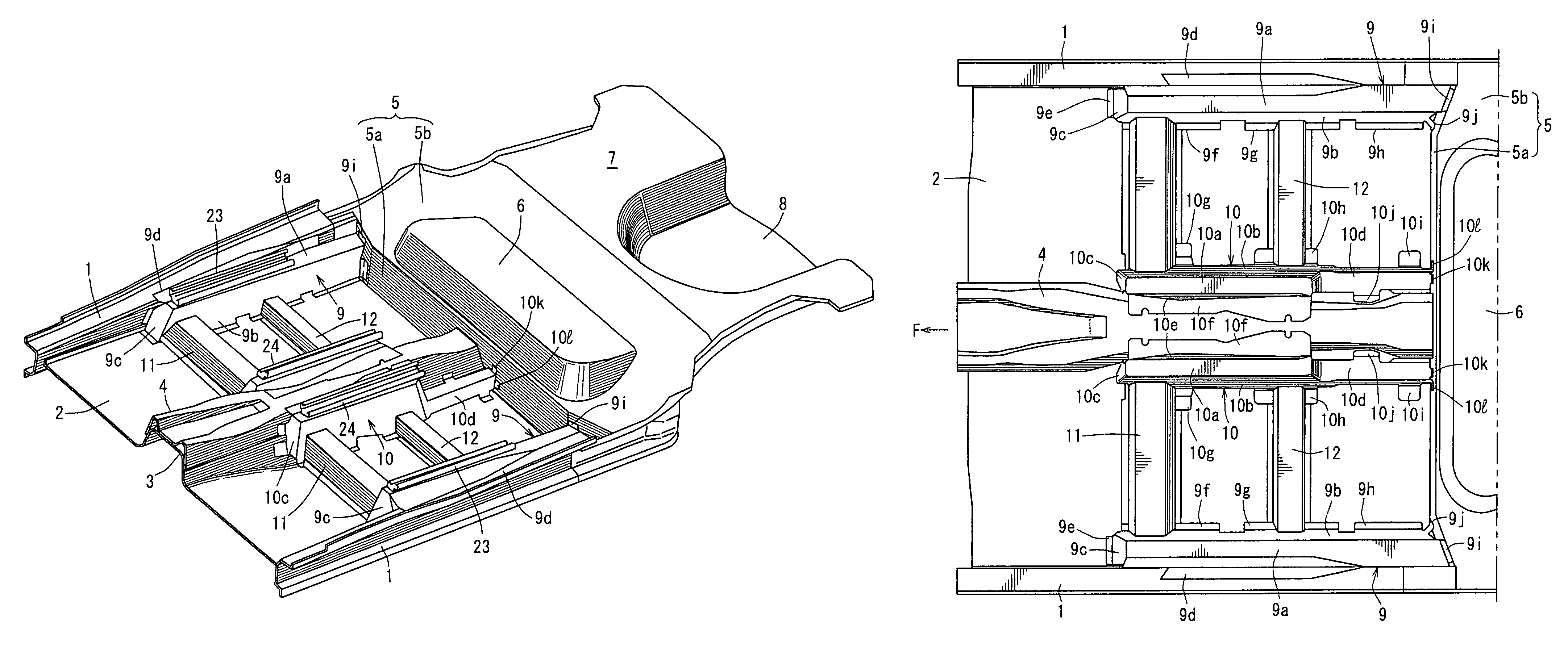
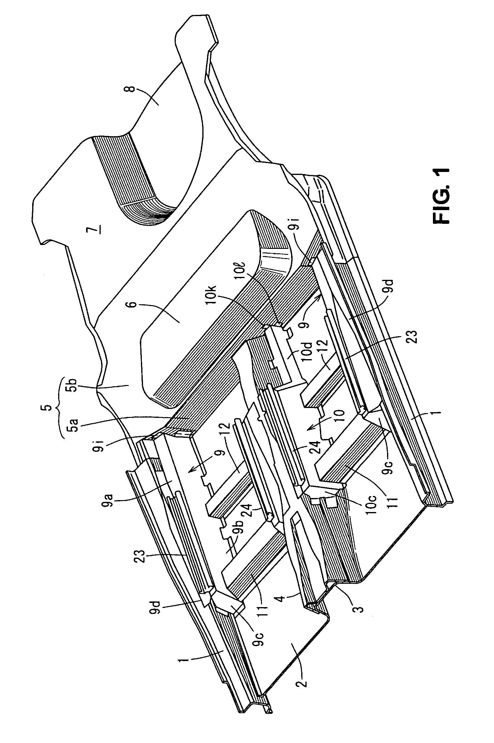
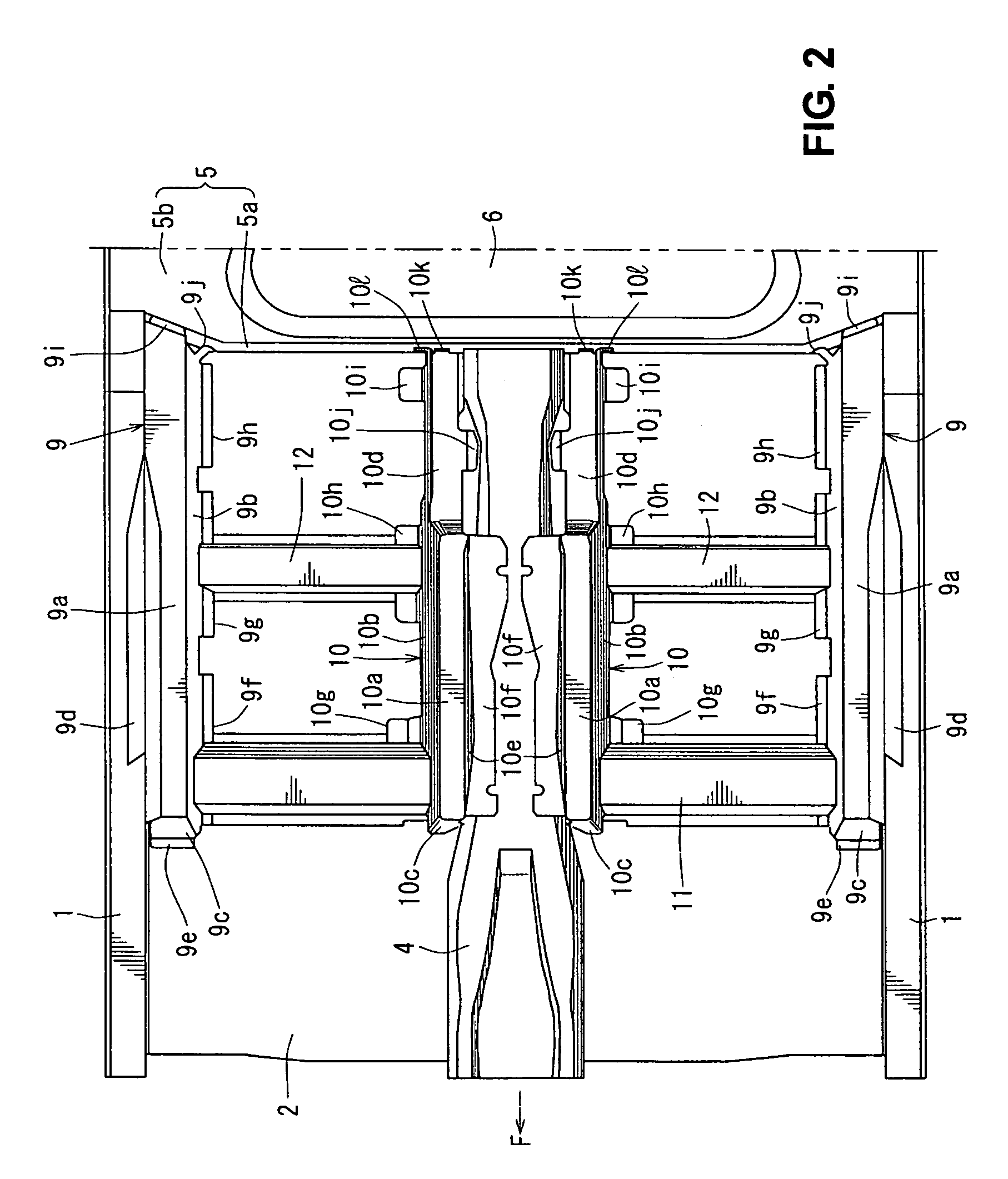
[0048]Hereinafter, preferred embodiments of the present invention will be described referring to the accompanying drawings. The figures show a lower vehicle body structure of a vehicle. FIG. 1 is a schematic perspective view showing an entire part of the lower vehicle body structure, FIG. 2 is a plan view of a major portion of FIG. 1, and FIG. 3 is an enlarged plan view of a right-half vehicle body structure of FIG. 2. In these figures, between a pair of floor panels 1, 1 (only a pair of side sill inners is illustrated in FIGS. 1-3) that extends longitudinally at both sides of the vehicle is provided a floor panel 2 substantially horizontally, which forms a lower face (floor face) of the vehicle body.

[0049]A tunnel portion 3, which projects upward and extends longitudinally, is formed integrally to a central portion of the floor panel 2. A tunnel member 4 (so-called high-mount backbone frame) is provided at a top of the tunnel portion 3 so as to extend longitudinally along the tunne...


PUM


Abstract

There is provided a lower vehicle body structure, in which a floor panel is provided between a pair of side sills extending longitudinally, a tunnel portion extending longitudinally is provided at a central portion of the floor panel, and a seat is provided between the side sill and tunnel portion, wherein there are provided a seat support member outer to support the seat, which extends longitudinally inside the side sill, and a plurality of cross members extending in the vehicle width direction with a specified distance therebetween longitudinally, outside end portions of which are connected to the seat support member outer and inside end portions of which are connected to the tunnel portion. Accordingly, both layout of the seat and sufficient vehicle body rigidity against a vehicle side crash can be provided.

Description

BACKGROUND OF THE INVENTION[0001]The present invention relates to a lower vehicle body structure of a vehicle, in which a floor panel is provided between a pair of side sills extending longitudinally, a tunnel portion extending longitudinally is provided at a central portion of the floor panel, and a seat for a passenger is provided between the side sill and the tunnel portion.[0002]Conventionally, the structures disclosed in Japanese Laid-Open Publication Nos. 2005-247003 and 2000-203449 are known as the above-described lower vehicle body structure.[0003]In these structures disclosed in the above publications, a pair of side sills extending longitudinally is provided, a floor panel is provided between these side sills, a tunnel portion extending longitudinally is provided at a central portion of the floor panel, a plurality of cross members extending in a vehicle width direction are provided on the floor panel with a specified distance therebetween longitudinally so as to interconn...

Claims


Application Information

Patent Timeline
Patent Type & Authority Patents(United States)
IPC IPC(8): B62D25/20
CPCB60N2/015B62D21/157B62D25/2036B62D25/025
Inventor MIZUMA, TAKASHIMORIYAMA, NAOMUNE
Owner MAZDA MOTOR CORP
Learn More